
2.1 Fuellox V2 R
2.1 Fuellox V2 R
[R] in the part number represents a Fuellox variant with an additional relay installed.
This overview demonstrates how to install or retrofit Fuellox to a mediaum size tank in the field.
2.1.1 Pulse Meter
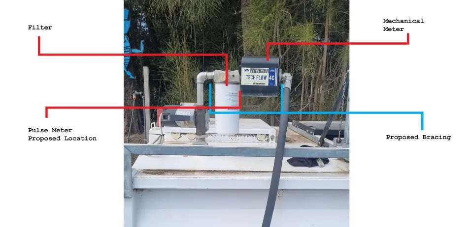
In this case a Piusi K24 meter is to be installed.
From this image we can see the Mechanical Meter and Filter are all suspended from the 1” pipework. This is not suitable to install a meter, as the meter body will rarely hold the weight of that equipment.
In a case such as this it is recommended to:
- install the pulse meter between the filter and the mechanical meter and
- make up a welded bracket to support the filter and mechancical meter.
This will ensure the meter does not have to support any weight nor take and shock from the hose movement.
2.1.2 Proposed Installation Layout
2.1.3 Main Power
12V DC supply is required to the Fuellox Input.
| Jumper Block | Pin Number | Pin Label | Name | Description |
|---|---|---|---|---|
| J9 | 1 | GND | Mains 0V | 12V -ve |
| J9 | 2 | +VBAT | Mains 12V | 12V +ve |
2.1.4 Pump Control
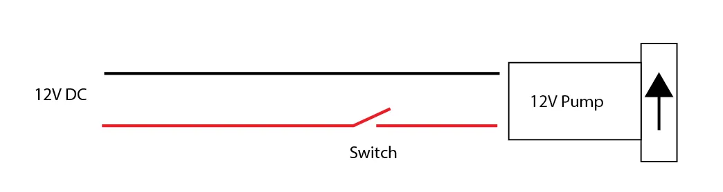
The 12VDC to the pump supply must be routed through the Fuellox Relay.
Take a suitable cable to deal with the power and current of the pump.
This diagram shows basic power to the pump, via a switch.
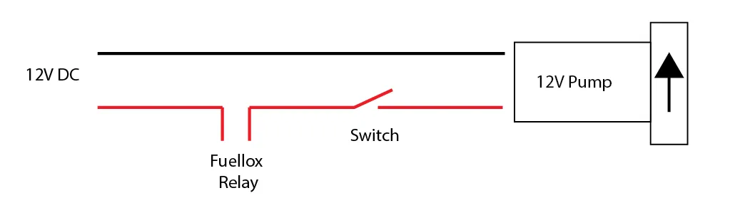
This diagram shows how the power is diverted via the Fuellox Relay to allow Fuellox to control the pump. In this configuration the pump would be left in the ON position so Fuellox can start and stop the pump.
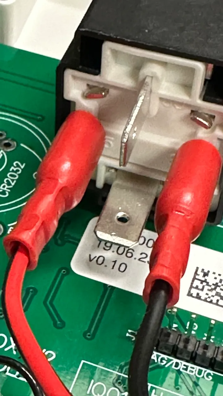
This image shows the relay. The relay has an open or close state, there is no input our output. Simple Open (default) or closed (energised).
2.1.5 Pulse Meter
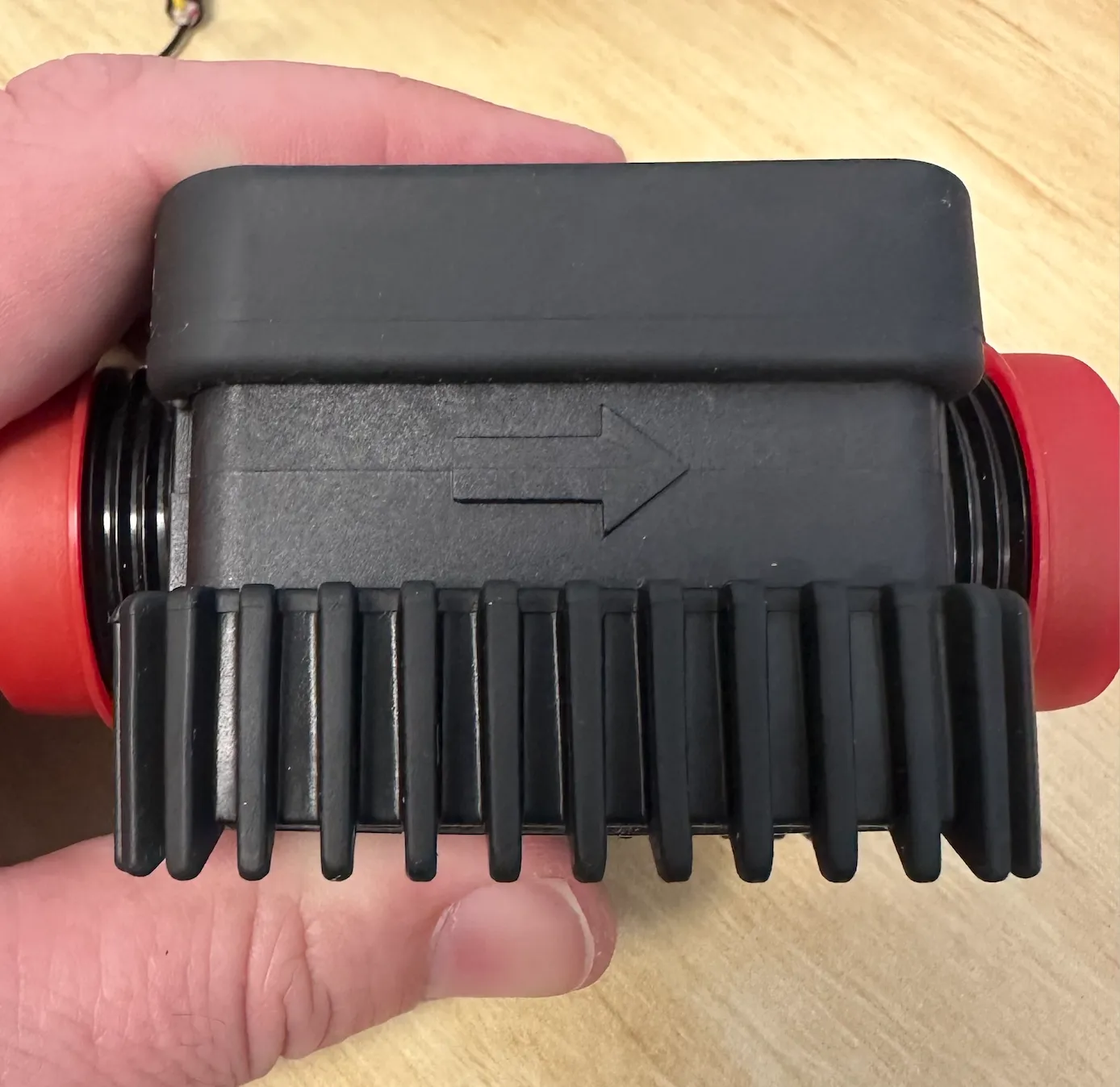
Be sure to consider the meters flow direction prior to installation.
2.1.5.1 Piusi K24
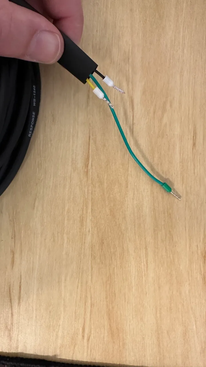
Reed pulse meters are wired to Signal and Ground. Optionally, but recommended, the meter cable should also use a shield.
This image shows a shielded cable with an additional lead wired to the shield layer within the cable assembly.
| Jumper Block | Pin Number | Pin Label | Name | Description |
|---|---|---|---|---|
| J18 | 3 | Pulse Input | Pulse Signal | |
| J18 | 4 | GND | Pulse Meter 0V | |
| J11 | 6 | Shield | Shield Wire | * Optional |
Insert the other wire ends to the meter body.
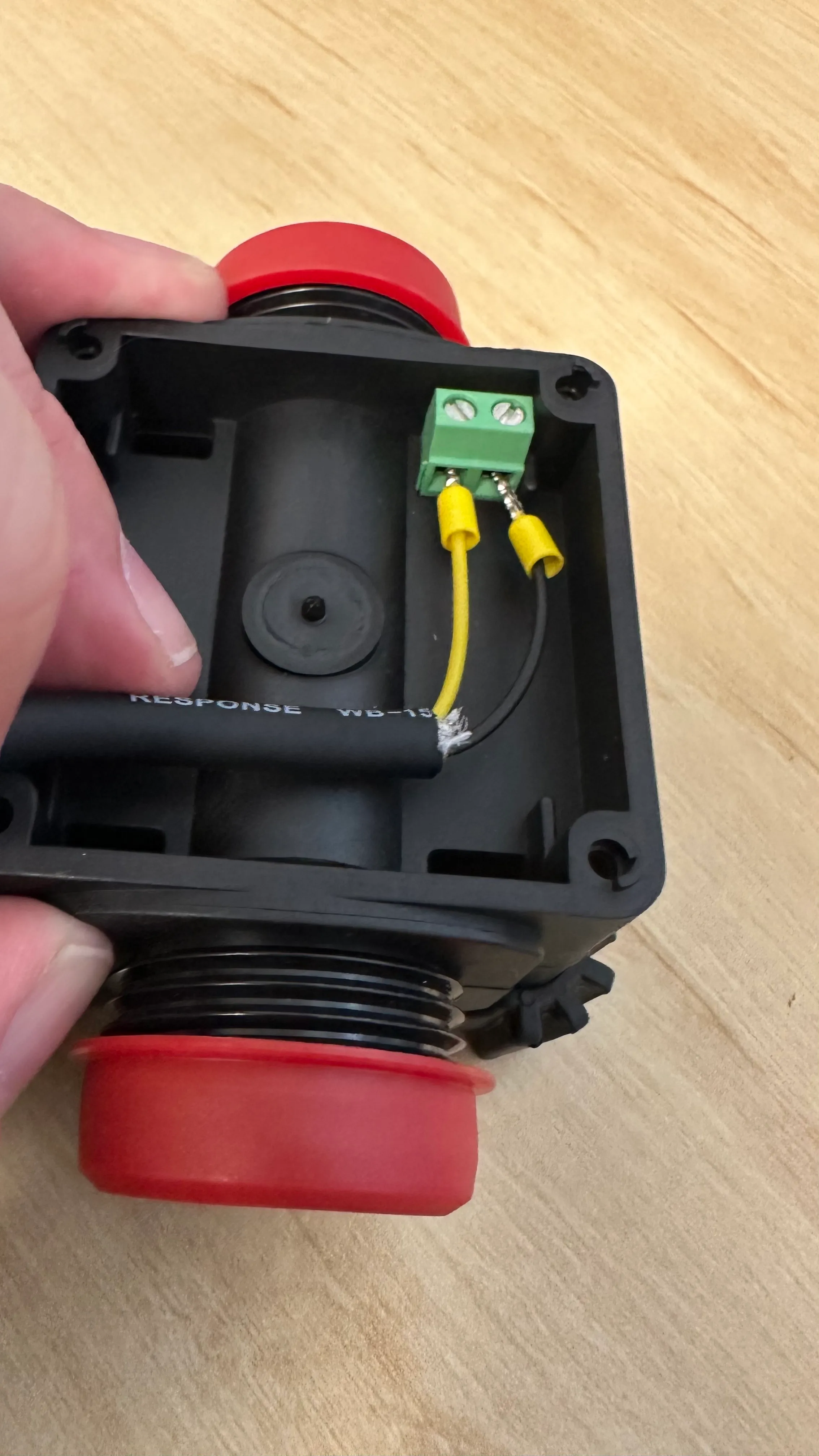
In the event there is no signal, try switching the meter wires at one end.
The calibration Factor for the meter is 87.73 pulse/l
2.1.5.2 SU304 Turbine Meter
These are a Hall Effect meter. Connect the 3 Wires to the Fuellox unit a follows. These meters do not ship with a shielded cable.
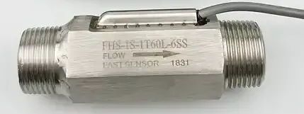
- Note meter markings may vary. Image for reference only.
| Jumper Block | Pin Number | Pin Label | Color | Name | Description |
|---|---|---|---|---|---|
| J18 | 2 | +V | Red | Power | |
| J18 | 3 | Pulse Input | Yellow | Pulse Signal | |
| J18 | 4 | GND | Black | Pulse Meter 0V |
The calibration Factor for the meter is 67.068 pulse/l
Note, the +V shall supply whatever voltage is provided to the Fuellox board. Choose the power supply carefully to ensure the meters power supply is optimal.
2.1.6 - Options
- Link to EStop and Nozzle Switch wiring
- Link to Level Wiring
- Link to calibration
- Link to Configuration