
V2 Wiring Reference
Wiring Reference
The following reference shall be used for Fuellox Wiring.
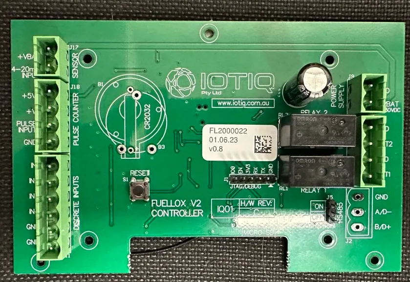
Board Image
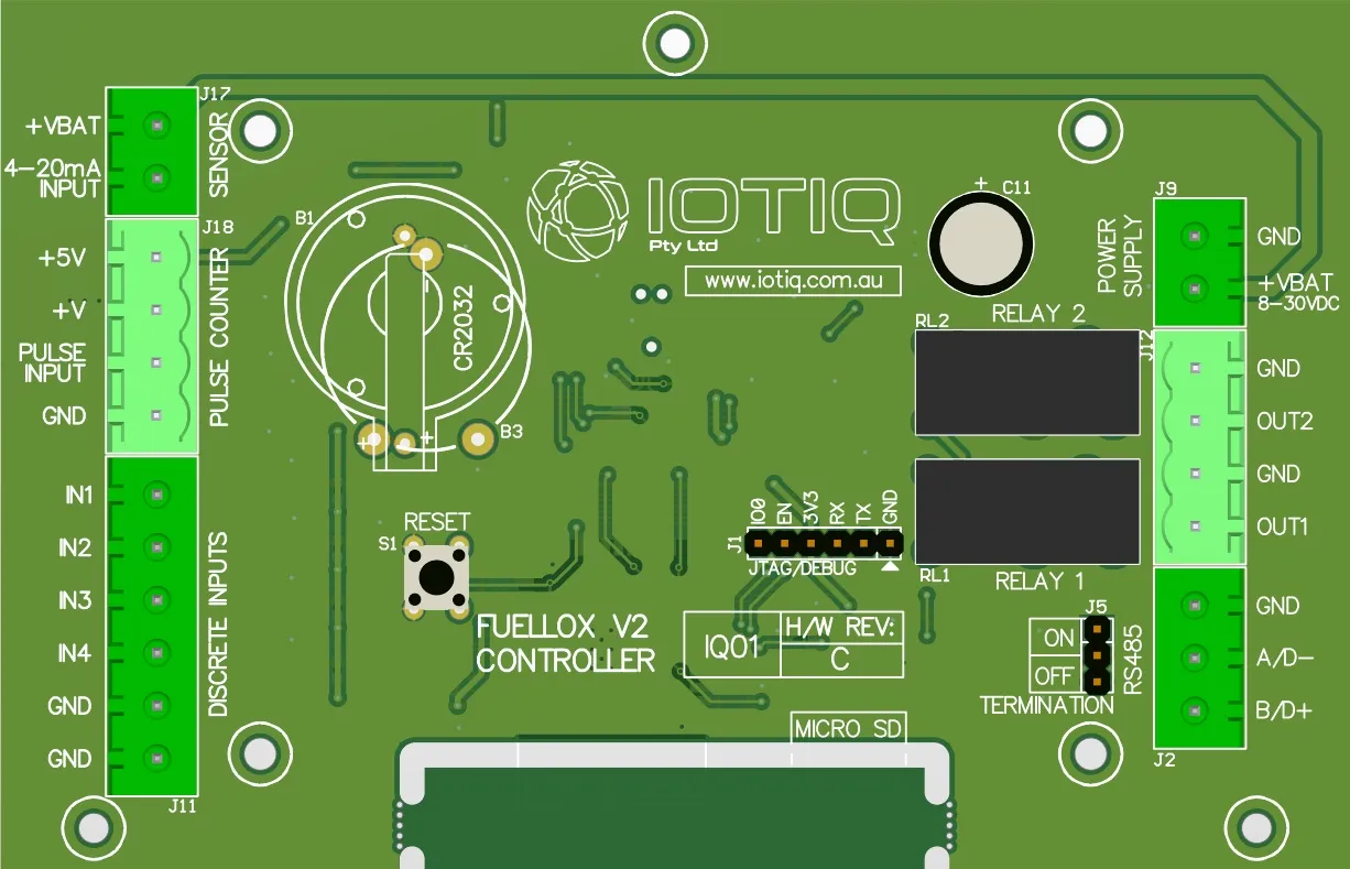
Board Layout
The main jumpers are shown here.
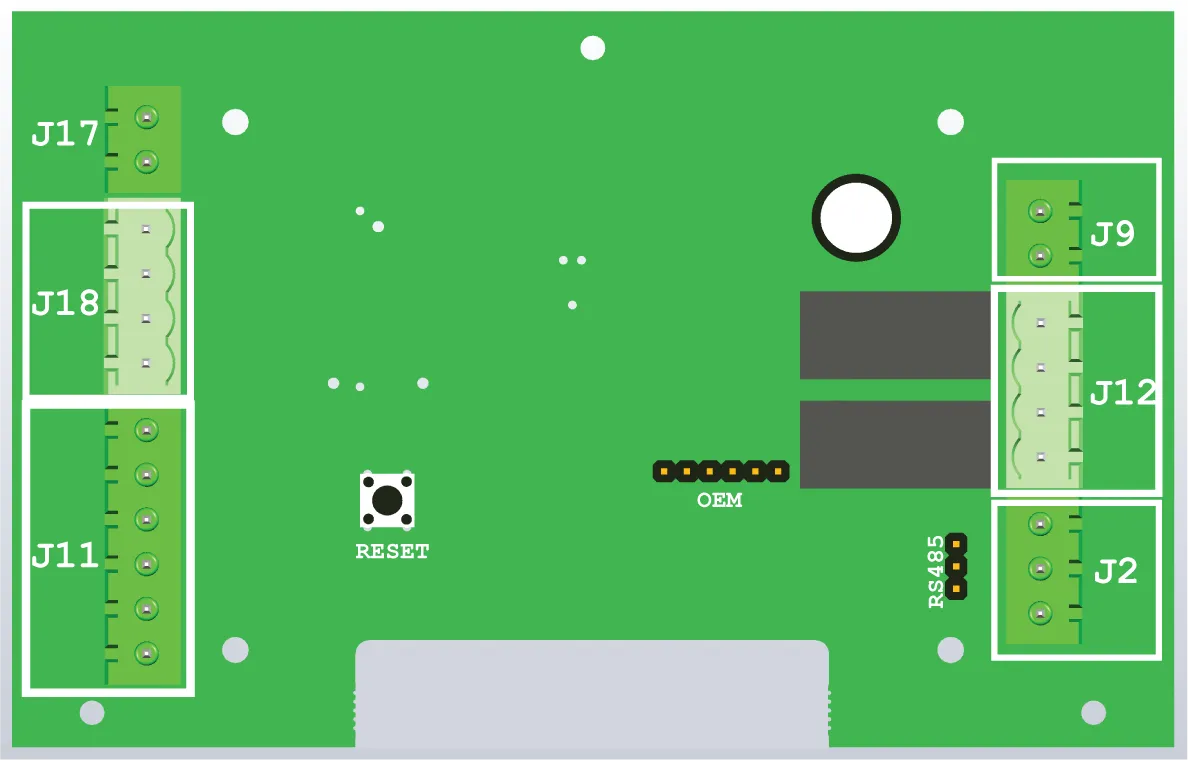
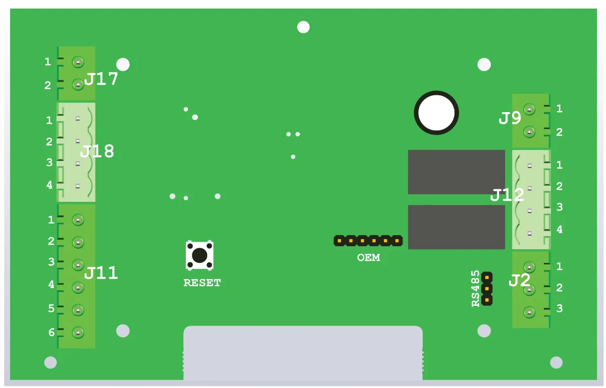
Board Detail
The jumpers are detailed as follows.
| Jumper Block | Pin Number | Pin Label | Name | Description |
|---|---|---|---|---|
| J2 | 1 | RS485 GND | RS485 GND | Future Use |
| J2 | 2 | RS485 A/0- | RS485 A/0- | Future Use |
| J2 | 3 | RS485 B/0+ | RS485 B/0+ | Future Use |
| J9 | 1 | GND | Mains 0V | 12V -ve |
| J9 | 2 | +VBAT | Mains 12V | 12V +ve |
| J11 | 1 | IN1 | Nozzle Switch | |
| J11 | 2 | IN2 | EStop NC | Normally Closed |
| J11 | 3 | IN3 | EStop NO | Normally Open |
| J11 | 4 | IN4 | Other TBA | |
| J11 | 5 | GND | Input 0v | |
| J11 | 6 | GND | Input 0v | |
| J12 | 1 | GND | Gnd Relay 2 | Secondary Relay 0V -ve |
| J12 | 2 | OUT2 | 12V Relay 2 | Secondary Relay Active + ve |
| J12 | 3 | GND | Gnd Relay 1 | Primary Relay 0V -ve |
| J12 | 4 | OUT1 | 12V Relay 1 | Primary Relay Active + ve |
| J17 | 1 | +VBAT | Level Sensor Supply | Power supply to the current loop sensor |
| J17 | 2 | 4-20mA input | Level Sensor Input | IO return for the variable current loop mA |
| J18 | 1 | +5V | Pulse Meter supply 5V +ve | |
| J18 | 2 | +V | Pulse Meter Supply 12V +ve | |
| J18 | 3 | Pulse Input | Pulse Signal | |
| J18 | 4 | GND | Pulse Meter 0V |
The Notation of J9-1 shall mean pin 1 on the J9 connector.