
3.1.3 Turbine Meters
3.1.3 Turbine Meter Wiring
In some cases smaller tanks require a low profile low cost meter. For these applications we offer a Turbine Meter.
Turbine meters are less accurate than positive displacement meters. Error of +/- 1% is to be expected
Always install the meter after the pump. Meters do not work on the suction side of the pump.
Where a filter is in use, install the meter after the filter.
3.1.3.1 Parts
| # | Part | Note |
|---|---|---|
| 1 | FLX-R | Fuellox with Relay (Note 1) |
| 2 | Meter | Turbine meter with hall effect |
| 3 | 12V | 12V power source, or 24V if the meter can also take 24V |
| - | Standard Fuellox | An additional relay is required |
Note 1: Standard Fuellox fused relay is 30 amp peak load. Relay’s should be oversized. Where higher current demands exist ensure a suitable relay is included.
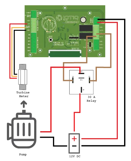
3.1.3.2 Wiring
| From | To | Description | Colour |
|---|---|---|---|
| 12V + | Fuellox VBat | Fuellox Power | Red |
| 12V + | 30 Relay Supply | Pump Active Power | Red |
| 12V - | Fuellox GND | Fuellox GND | Black |
| 12V - | Pump GND | Pump GND | Black |
| Relay Active | 87 Pump Supply | Pump GND | Black |
| Pulse 12V | Meter Red | Red | |
| Pulse signal | Meter Yellow | Yellow | |
| Pulse 0V | Meter Black | Black | |
| Fuellox Out 1 | 86 Relay Coil | White | |
| GND | 85 Relay Coil 0v | White |
Wiring Diagram
3.1.4 Optional Emergency Stop
Source a dual pole switch with latching Normally Open and Normally Closed.
The Normally Closed channel will operate between the Relay Active and Pump 12V supply
The Normally Open channel will run between the Fuellox Input (IN1-IN4) and GND
The EStop must be enabled in the Device Configuration.
3.1.5 Calibration
Turbine meters are accurate to +/- 2%. They can be calibrated using normal methods. At times the normal calibration method, using a claibrated jug may not be suitable.
Calibration by weight
Start with a heavy duty scale. A calibrated scale should be used, or at least the most accurate scale possible.
Ensure the scale reports 1 or 2 decimals. Ensure the scale weight range suits the mass to weigh
- ie. If you intend to weigh 20L of Diesel, do not use a scale with a max weight of 20kg
- Zero the scale
- Weight the mass of the empty container
- Fill the container and weigh the total
- Deduct the container mass from the measurement to get the amount of fuel by weight
- Divide the wight, by the diesel density.
- The fuel density should be reported on the fuel delivery docket
- You now have the actual fuel volume.
Repeat the process 3 times to ensure consistent results and take a note of that information.
The help desk can assist you to apply that calibration information.
Fuellox Calibration
- Enter the Manage Devices menu
- Connect to the Fuellox Device
- Go to the Calibrate Section
- Choose the transaction that you wish to use for the calibration
- Enter the actual volume
- Fuellox will calculate and update the device calibration
Test the new calibration
Empty the calibration vessel. Repeat the dispense and calculation above Confirm the volume by weight matches the Fuellox reported volume to within 2%