App Setup
Legacy Systems
Ths guide is not compatible with Legacy Fuellox hardware and applies solely to V2 units.
Fundamentals
The 4-20mA sensor produces a linear relationship across the sensor range.
| Sensor Value | Liquid Depth (H2O) |
|---|---|
| 4 mA | 0 mm |
| 20 mA | 3,000 mm |
There is however an adjustment required where the fluid density is not 1.0 kg/L
The typical density of diesel fuel is 0.85 - 0.87 kg/L.
The corrected table for a diesel tank, assuming a max height of a containerized tank of 2.7m is therefore
| Sensor Value | Liquid Depth (ADF) |
|---|---|
| 4 mA | 0 mm |
| 21 mA | 2,700 mm |
*ADF = Automotive Distillate Fuel or Diesel
In Fuellox we assume the tank bottom is going to be a few hundred litres when its empty.
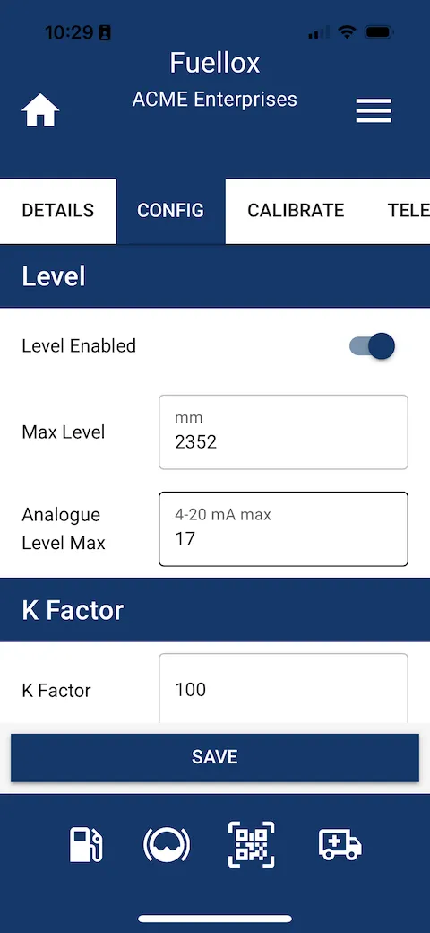
Bluetooth Config for Level
The simplest way to apply the tank level calibration to the hardware is via the app.
Enter the Manage Devices section:
- Select and connect to the device
- Set the parameters above in the app [note that the 16,652 is converted/rounded to 17 for the hardware]
- Click Save
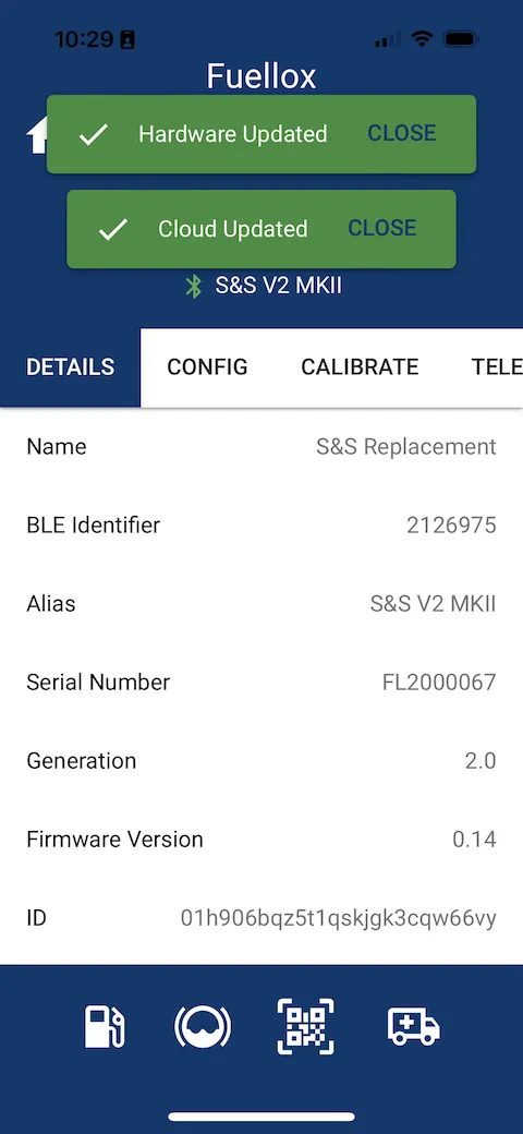
- Await the 2x Green notifications
- Power Cycle the unit
Apply new settings
Data Updated
Illumination of Error LED
If you update the level system and see the Error LED right after reboot, it indicated the sensor is dry and not submerged. If the error persists after the fuel is supplied, the sensor may be wired the wrong way around. Switch the polarity of the sensor.
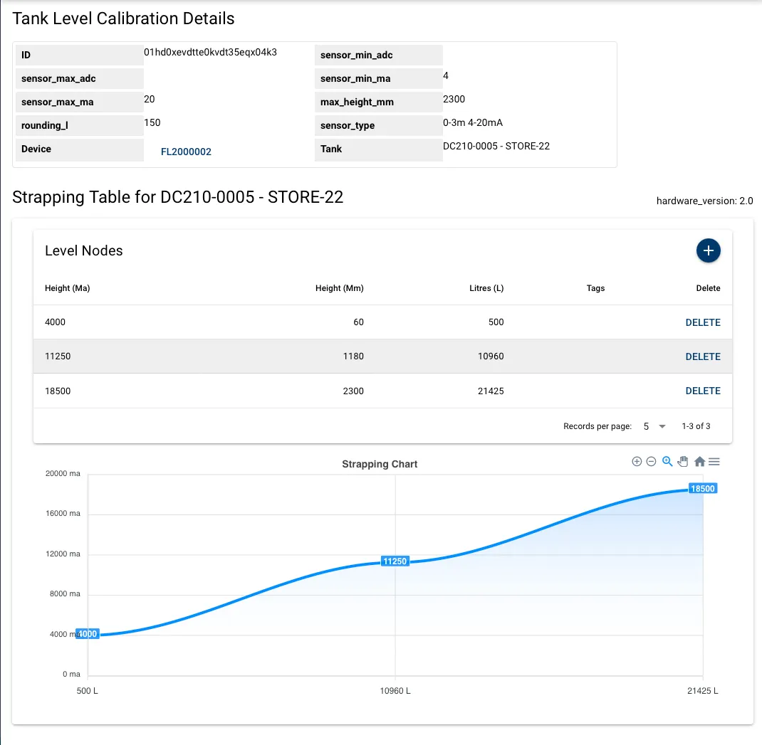
Configuration of Website Strapping Data
- Admin access is required.
- Level tables can’t be applied from the Simplified View. Toggle the view the Default.
- All new systems are to use the Tank Level Calculation Version 3
Overview
Here are the steps to activate level on the main dashboard.
- Create the Tank
- Apply the Warning and Reorder levels
- Add the Tank Capacity
- Edit the Device
- Update the capacity
- Add the Tank Level Calibration
- Apply the settings:
- sensor min ma = 4,000
- sensor max ma = [upper sample ma]
- min height = lowest mm from the dip stick. Say 100mm. Never 0
- max height = [upper sample mm]
- rounding. To be determined based on the tank, and the quality of the strapping table. Start with 250L
- Click save
- From the Tank Level Calibration Details page, add the level nodes
- Add the 3 nodes from the upper, mid and lower points
- the mA values are in 000’s