Level Setup and Calibration
Legacy Systems
Ths guide is not compatible with Legacy Fuellox hardware and applies solely to V2 units.
Theory
The 4-20mA sensor produces a linear relationship across the sensor range.
| Sensor Value | Liquid Depth (H2O) |
|---|---|
| 4 mA | 0 mm |
| 20 mA | 3,000 mm |
There is however an adjustment required where the fluid density is not 1.0 kg/L
The typical density of diesel fuel is 0.85L/kg.
The corrected table for a diesel tank, assuming a max height of a containerized tank of 2.7m is therefore
| Sensor Value | Liquid Depth (ADF) |
|---|---|
| 4 mA | 0 mm |
| 21 mA | 2,700 mm |
*ADF = Automotive Distillate Fuel or Diesel
In Fuellox we assume the tank bottom is going to be a few hundred litres when its empty.
Strapping Tables
A Strapping table is a list of measurements from a tank that relate the height of liquid to a volume.
Where a tank has linear sides that strapiong table will be linear. In this case 3 sample points are required for Fuellox. Top, bottom and a mid point.
Where the tank has rounded ends, sloped bottoms, non uniform walls, or curved features additional strapping points should be used.
Creating many data points, when the actual tank sensor max hiehgt is unknown will lead to major errors in the calculation of level.
Ensure that when theoretical data is used to establish a tank level calibration:
- Excess data points are not used
- Revisit the level calculation performance when fuel is delivered
- Compare calculated vales to actual prior to ‘signing off’ the final table
Level Sensor values
These values are based on estimates only, and shall be reviewed as more reliable data is produced within the platform
| Liquid Diesel (m) | Sensor mA |
|---|---|
| 0.00 | 4,000 |
| 0.29 | 5,860 |
| 0.59 | 7,710 |
| 0.88 | 9,570 |
| 1.18 | 11,430 |
| 1.47 | 13,290 |
| 1.76 | 15,140 |
| 2.06 | 17,000 |
| 2.35 | 18,860 |
| 2.65 | 20,000 |
Strapping Table Estimate
So for a tank of height 1200mm, and a volume of 10,000L:
| Diesel Height (mm) | Sensor Value (mA) | Volume (L) | note |
|---|---|---|---|
| 100 | 4,100 | 150 | [Lower sample] |
| 650 | 7,765 | 5,075 | [Mid Point] |
| 1,200 | 11,430 | 10,000 | [Upper Sample] |
This table is generated by taking:
- The min volume from the dip stick, must not be 0 [Lower sample]
- The Safe Fill Litres and max depth
- The sensor max based on the liquid height [Upper Sample]
- The mid point of the upper and lower samples [Mid Point]
The Fuellox Hardware configuration is therefore going to be:
Level Probe: On Max Level mm: 1200 Max ADC: 11430
| Feature | Default Value | unit |
|---|---|---|
| Level Installed | TRUE | Boolean |
| Max Level | 1200 | mm max |
| Max Analogue | 11430 | mA max |
The values are to be applied to the device prior to wet commissioning and must be tested once the tank is filled.
Real data test
To get a real sample from the max fill:
- Fill the tank to the SFL
- Dispense fuel from the tank. Recirculation is fine
- Stop the transaction
- Moinitor the recorded data in the platform for the max sensor value in mA, with the actual Vol L and mm
- Apply that as the [Upper Sample]
- recalculate the [Mid Point]
Mid point Calculation
Simply apply and average calculation
| Point | mA value | mm Value |
|---|---|---|
| Lower | 4,100 | 200 |
| Upper | 15,900 | 2,200 |
| Mid | 10,000 | 1,200 |
| math | (4,100 + 15,900) / 2 | (200 + 2,200) / 2 |
| cont. | 20,000 / 2 | 2400 / 2 |
Full Working Example
Here we demonstrated how to create a complete Tank Level Calibration.
Lets assume the first few data samples have come back from the sensor. A level of 25900L is reported with a tank liquid height of 2352mm and a sensor reading on 16,662.
Observation Data
| Parameter | Value |
|---|---|
| Height | 2,352 mm from Dip Stick |
| Volume | 25,900L from Dip Stick |
| Sensor | 16,662 from Fuellox Data, actual recorded value |
This sample point is our maximum.
Theoretical Minimum
| Parameter | Value |
|---|---|
| Height | 100 mm from Dip Stick |
| Volume | 300L from Dip Stick |
| Sensor | 4,100 Low range of sensor |
This sample point is our theoretical minimum. The level data will be enhanced by taking an actual mimumum as above. ie Real dip measurements for volume and mm along with an actual corresponding sensor value.
Calculating Midpoint Values
Let’s calculate the midpoint between the two given diesel heights and then determine the sensor value and volume at that point. We will then find the sensor value and volume at a diesel height of 1500mm. I’ll use linear interpolation to estimate these values.
- Find the midpoint height between 100mm and 2352mm:
- Find the midpoint sensor between 4100ma and 16662mA:
- Find the midpoint Volume between 300L and 25,900L:
| Diesel Height (mm) | Sensor Value (mA) | Volume (L) | Note |
|---|---|---|---|
| 100 | 4,100 | 300 | Lower sample |
| 1,226 | 10,381 | 13,100 | Midpoint |
| 2,352 | 16,662 | 25,900 | Upper sample (Actual) |
These values are approximations and might need to be adjusted based on a more detailed model or additional data points for accuracy.
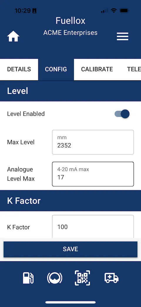
Bluetooth Config for Level
The simplest way to apply the tank level calibration to the hardware is via the app.
Enter the Manage Devices section:
- Select and connect to the device
- Set the parameters above in the app [note that the 16,652 is converted/rounded to 17 for the hardware]
- Click Save
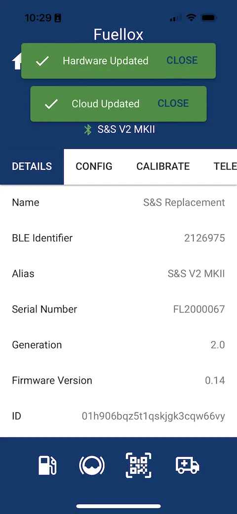
- Await the 2x Green notifications
- Power Cycle the unit
Apply new settings
Data Updated
Illumination of Error LED
If you update the level system and see the Error LED right after reboot, it indicated the sensor is dry and not submerged. If the error persists after the fuel is supplied, the sensor may be wired the wrong way around. Switch the polarity of the sensor.
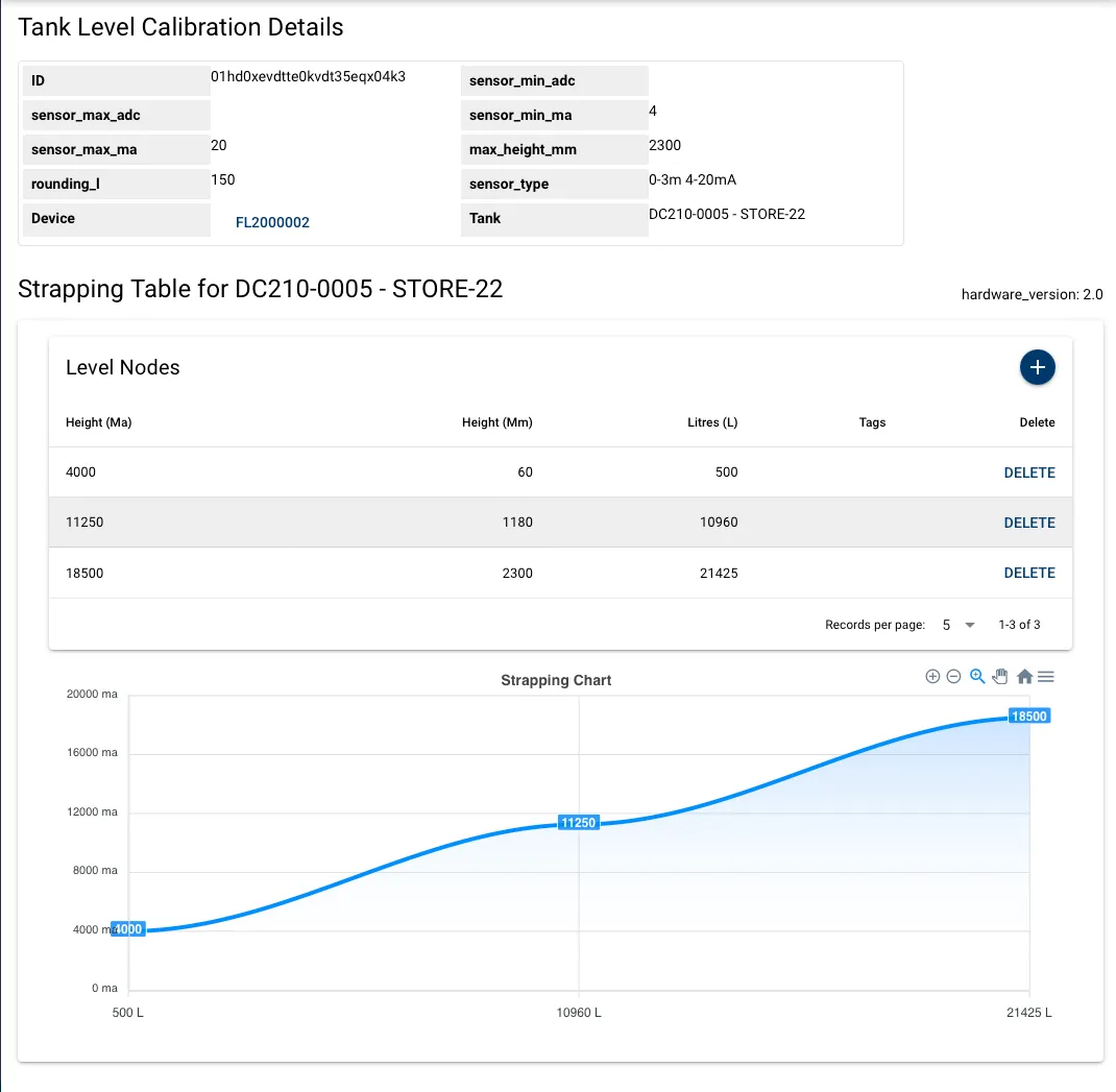
Configuration of Website Strapping Data
- Admin access is required.
- Level tables can’t be applied from the Simplified View. Toggle the view the Default
Overview
Here are the steps to activate level on the main dashboard.
- Create the Tank
- Apply the Warning and Reorder levels
- Add the Tank Capacity
- Edit the Device
- Update the capacity
- Add the Tank Level Calibration
- Apply the settings:
- sensor min ma = 4,000
- sensor max ma = [upper sample ma]
- min height = lowest mm from the dip stick. Say 100mm. Never 0
- max height = [upper sample mm]
- rounding. To be determined based on the tank, and the quality of the strapping table. Start with 250L
- Click save
- From the Tank Level Calibration Details page, add the level nodes
- Add the 3 nodes from the upper, mid and lower points
- the mA values are in 000’s