Setting Up the App
Legacy Systems
This guide is not compatible with legacy Fuellox hardware and is intended exclusively for V2 units.
Fundamentals
The 4–20 mA sensor delivers a linear output proportional to the measured parameter across its full operating range.
| Sensor Value | Liquid Depth (H₂O) |
|---|---|
| 4 mA | 0 mm |
| 20 mA | 3,000 mm |
Adjustments are necessary when the fluid density differs from the standard value of 1.0 kg/L.
The typical density of diesel fuel ranges between 0.85 and 0.87 kg/L.
Accordingly, the corrected table for a diesel tank—assuming a maximum height of 2.7 m in a containerized setup—is as follows:
| Sensor Value | Liquid Depth (ADF) |
|---|---|
| 4 mA | 0 mm |
| 21 mA | 2,700 mm |
In Fuellox systems, it is assumed that the tank bottom will still contain a few hundred litres of fuel when considered ‘empty’.
Bluetooth Configuration for Level Calibration
The most straightforward method for applying tank level calibration to the hardware is through the mobile app.
To configure the device via Bluetooth, follow these steps in the Manage Devices section:
-
Select and connect to the device.
-
Enter the specified parameters into the app.
-
Tap Save.
-
Wait for two green notifications to confirm successful update.
-
Power cycle the unit to apply the changes.
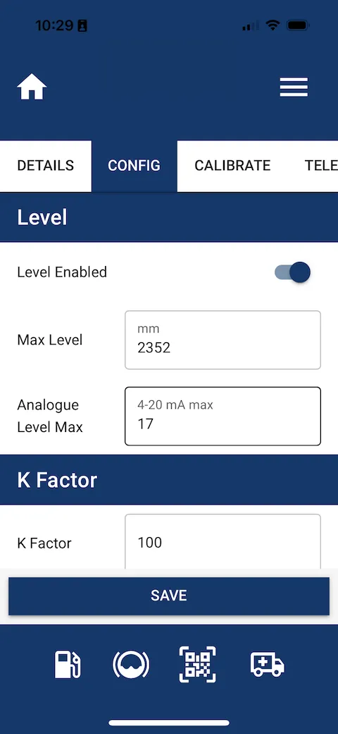
Applying New Settings
The following image shows the configuration screen in the Fuellox app where level settings, analogue max value, and K Factor are applied and saved.
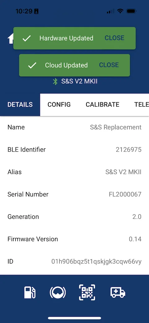
Data Updated
The following image shows the confirmation screen in the Fuellox app indicating that both hardware and cloud data have been successfully updated, along with key device details such as BLE Identifier, Serial Number, and Firmware Version.
Error LED Illumination
If the Error LED illuminates immediately after rebooting the level system, it usually indicates that the sensor is dry and not submerged.
If the error persists even after fuel has been added, the sensor may be incorrectly wired. In this case, reverse the sensor polarity to correct the issue.
Configuration of Website Strapping Data
-
Admin access is required.
-
Level tables cannot be applied in Simplified View. Ensure the view is toggled to Default.
-
All new systems must use Tank Level Calculation Version 3.
Tank Calibration Steps
Follow these steps to activate the tank level on the main dashboard:
-
Create the Tank
-
Set the Warning and Reorder levels.
-
Enter the Tank Capacity.
-
-
Edit the Device
- Update the Capacity field.
-
Add Tank Level Calibration
-
Apply the Calibration Settings
-
sensor min mA = 4,000
-
sensor max mA = [upper sample mA]
-
min height = Distance from the bottom of the dipstick (e.g., 100 mm). Never set this to 0.
-
max height = [upper sample mm]
-
rounding = Depends on the tank and strapping table quality. Start with a value of 250 L.
-
Click Save.
-
-
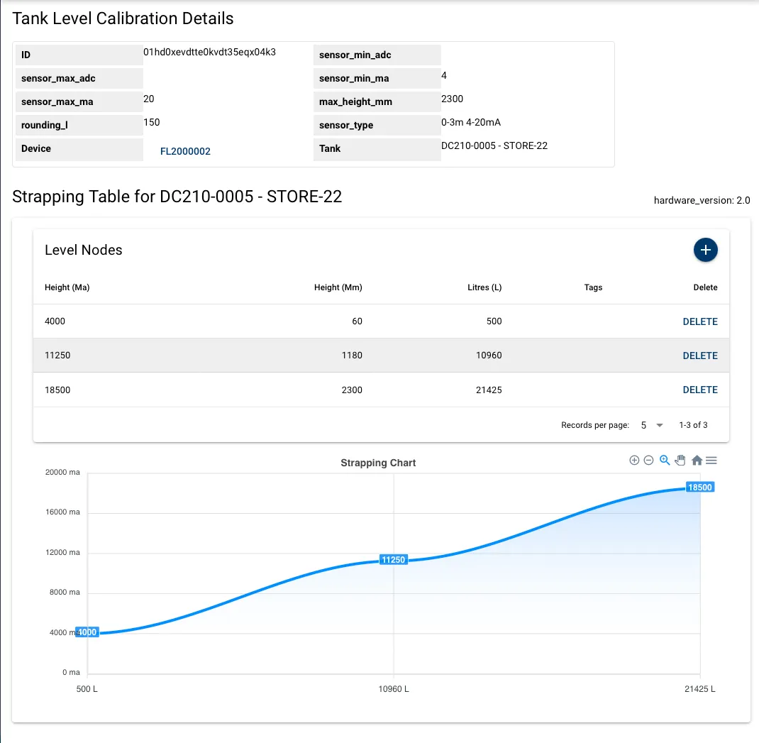
Add Level Nodes from the Tank Level Calibration Details page.
-
Add three nodes: upper, middle, and lower points.
-
Make sure mA values are entered in thousands (000’s format).
-