
Portable Solenoid Control (SO) Installation Guide
What You Need
To install and configure the Fuellox Portable (Compact SKU), ensure you have the following:
Required Items:
- Fuellox Portable (Compact SKU) unit
- Mounting Assembly (to secure the unit in place)
- Pulse Meter & Calibration Details (e.g., pulse per liter for accurate flow measurement)
- Solenoid Valve (for fuel flow control)
- Pump & Hoses (for fuel delivery)
- Basic Tools (e.g., drill, wrenches, screwdrivers, cable ties)
- Smartphone with Fuellox App (for system setup and monitoring)
- User Role: “Device Management” (assigned to the user managing the device)
Optional Components:
Depending on your installation requirements, you may also refer to the Product Accessories section for all accessories of the products.
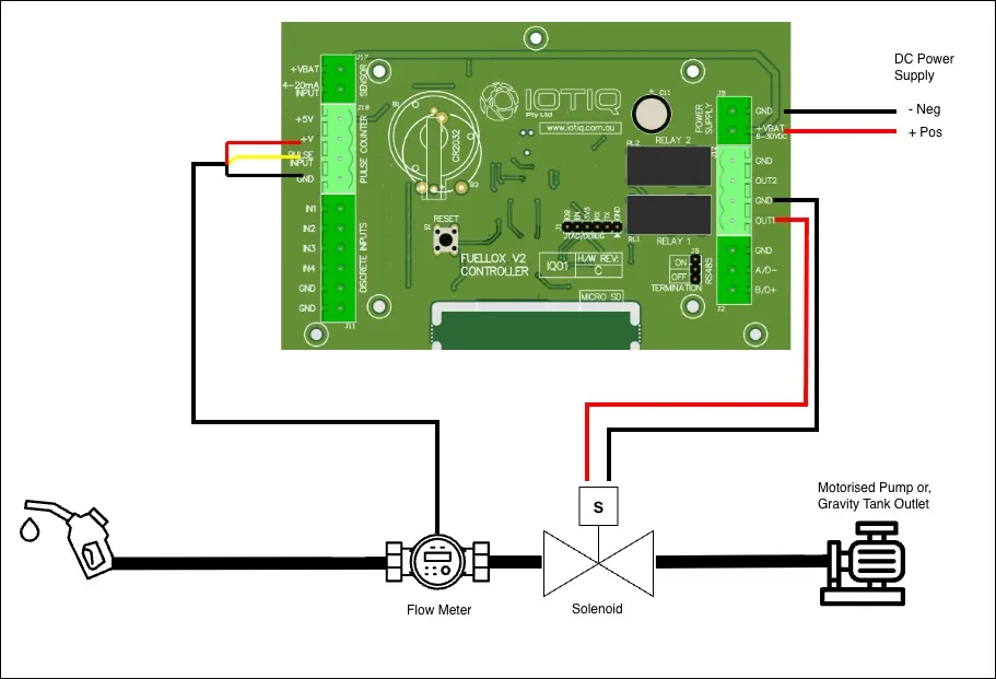
Proposed Installation Layout
Main Power
A regulated 12V DC power supply is required for the Fuellox input.
| Jumper Block | Pin Number | Pin Label | Name | Description |
|---|---|---|---|---|
| J9 | 1 | GND | Mains 0V | 12V -ve |
| J9 | 2 | +VBAT | Mains 12V | 12V +ve |
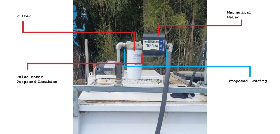
Pulse Meter Installation
Make sure the flow direction of the pulse meter is correctly aligned before installation for accurate and reliable operation.
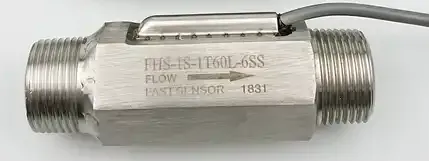
SU304 Turbine Meter
The SU304 is a Hall Effect turbine meter. It connects to the Fuellox unit using three wires, as outlined below. Please note that these meters are not supplied with shielded cables.
SU304 Turbine Meter wiring Details
| Jumper Block | Pin Number | Pin Label | Color | Name | Description |
|---|---|---|---|---|---|
| J18 | 2 | +V | Red | Power | |
| J18 | 3 | Pulse Input | Yellow | Pulse Signal | |
| J18 | 4 | GND | Black | Pulse Meter 0V |
The calibration factor for this meter is 67.068 pulses per litre (pulse/L).
Piusi K24
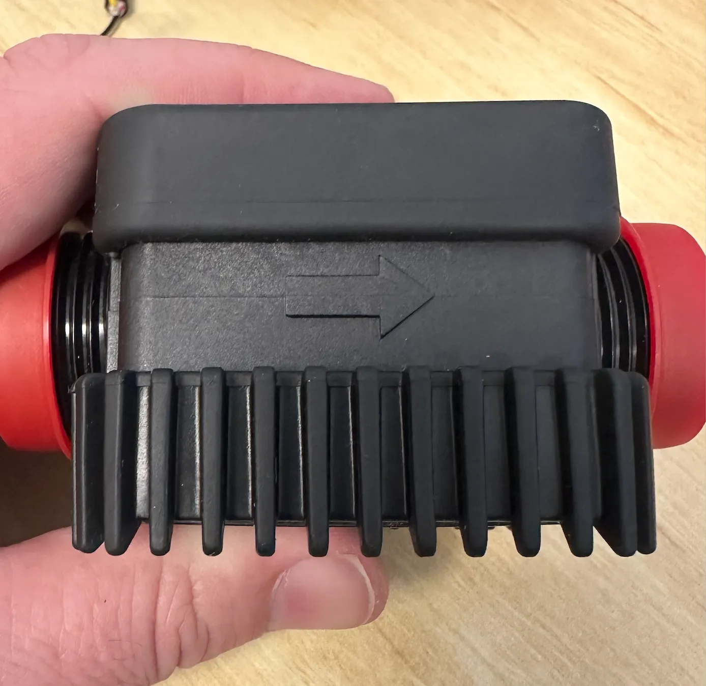
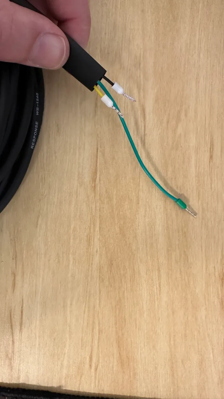
Reed pulse meters are connected using Signal and Ground wires. While optional, it is strongly recommended to use a shielded cable for improved signal integrity and noise reduction.
The image below illustrates a shielded cable, where an additional lead is connected to the shielding layer within the cable assembly.
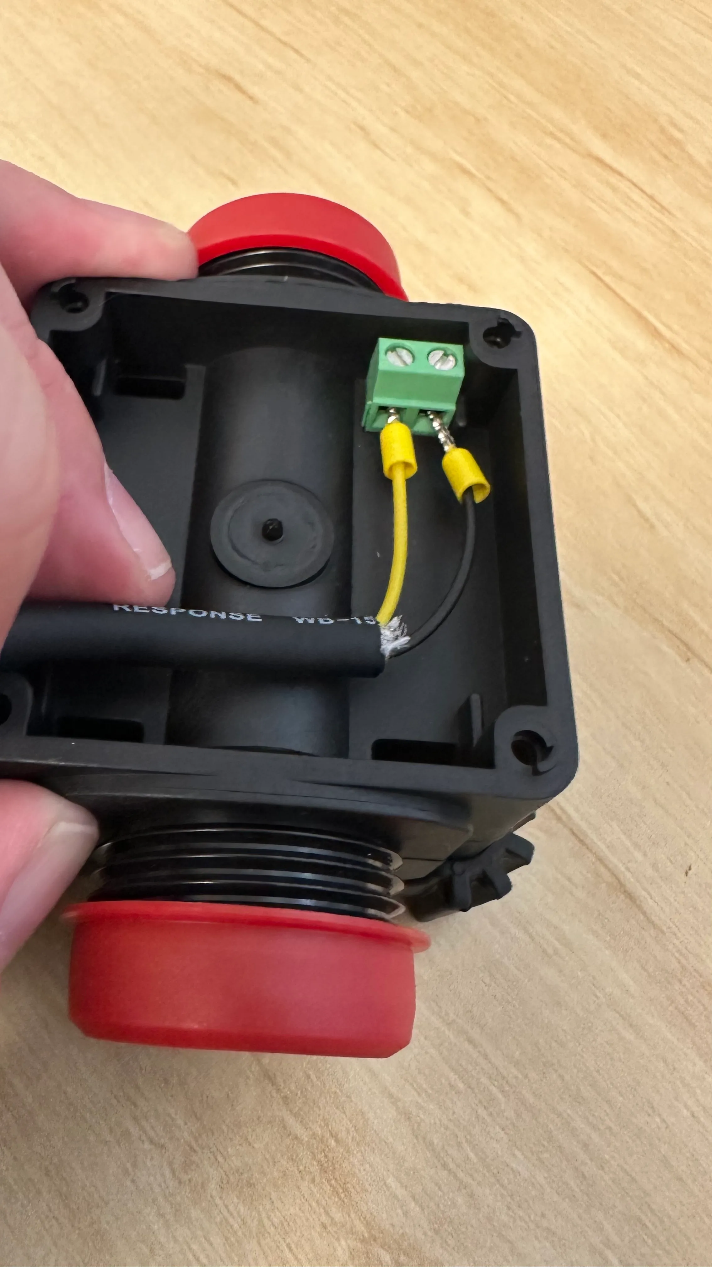
Pulse Meter Wiring Details
The table below outlines the recommended pin assignments for connecting a pulse meter to the system. Use a shielded cable for best performance, with the shield connection being optional but recommended.
| Jumper Block | Pin Number | Pin Label | Name | Description |
|---|---|---|---|---|
| J18 | 3 | Pulse Input | Pulse Signal | |
| J18 | 4 | GND | Pulse Meter 0V | |
| J11 | 6 | Shield | Shield Wire | Optional |
Connect the other ends of the wires to the corresponding terminals on the pulse meter body, ensuring proper signal and ground alignment.
The calibration factor for this meter is 87.73 pulses per litre (pulse/L).
Options
The following optional features are available for extended functionality. Refer to the linked sections below for wiring and configuration details:
Return to Getting Started