
Turbine Meters
Turbine Meter Wiring
In certain applications—particularly with smaller tanks—a low-profile, cost-effective solution is preferred. For these scenarios, a Turbine Meter is an ideal option.
-
Turbine meters offer a compact and affordable alternative, though they are less accurate than positive displacement meters. A typical accuracy variance of ±1% should be expected.
-
Installation best practice requires positioning the meter after the pump, as turbine meters are not designed to function effectively on the suction side.
-
When a filter is installed, make sure the meter is placed downstream of the filter to maintain accuracy and avoid flow disruption.
Parts
| # | Part | Note |
|---|---|---|
| 1 | FLX-R | Fuellox with Relay (Note 1) |
| 2 | Meter | Turbine meter with hall effect |
| 3 | 12V | 12V power source, or 24V if the meter can also take 24V |
| - | Standard Fuellox | An additional relay is required |
Wiring
| From | To | Description | Colour |
|---|---|---|---|
| 12V + | Fuellox VBat | Fuellox Power | Red |
| 12V + | 30 Relay Supply | Pump Active Power | Red |
| 12V - | Fuellox GND | Fuellox GND | Black |
| 12V - | Pump GND | Pump GND | Black |
| Relay Active | 87 Pump Supply | Pump GND | Black |
| Pulse 12V | Meter Red | Red | |
| Pulse signal | Meter Yellow | Yellow | |
| Pulse 0V | Meter Black | Black | |
| Fuellox Out 1 | 86 Relay Coil | White | |
| GND | 85 Relay Coil 0V | White |
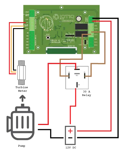
Wiring Diagram
The following diagram shows how the Fuellox controller connects to a turbine meter, 30A relay, and 12V DC power to control pump operation.
Optional Emergency Stop
Install a dual-pole switch with latching Normally Open (NO) and Normally Closed (NC) contacts.
- The Normally Closed channel should be wired between the Relay Active line and the Pump 12V supply.
- The Normally Open channel should be connected between the Fuellox Input (IN1–IN4) and GND.
Calibration
Turbine meters usually offer accuracy within ±2%. While standard calibration methods are generally sufficient, using a calibrated jug may not always be appropriate for every scenario.
Calibration by weight
Begin with a heavy-duty, calibrated scale—preferably one that offers high precision and reports at least one or two decimal places. The selected scale should be suitable for the expected weight range.
For example: If calibrating for 20L of diesel, avoid using a scale with a 20kg maximum capacity.
Steps
-
Zero the scale.
-
Weigh the empty container.
-
Fill the container with fuel and weigh the total.
-
Subtract the empty container’s weight from the total to determine the fuel’s weight.
-
Divide the fuel weight by the fuel’s density (refer to the density on the fuel delivery docket) to calculate actual fuel volume.
-
This value is your actual fuel volume for calibration purposes.
Fuellox Calibration
To calibrate your Fuellox device, please refer to the Calibration guide for detailed instructions and step-by-step guidance.
Verifying the Calibration
To confirm the accuracy of the new calibration:
-
Empty the calibration vessel.
-
Repeat the dispense and measurement process as outlined previously.
-
Make sure the measured volume (by weight) aligns with the volume reported by Fuellox, within a margin of ±2%.