
Setting Up Level Module
Fundamentals
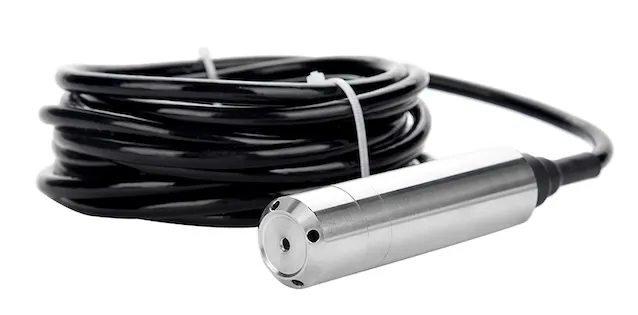
The Fuellox Level Gauge (LG) is a submersible sensor designed to be placed directly in the fuel. Functioning as a pressure sensor, it determines the liquid level by measuring the pressure exerted by the diesel.
Each time fuel is dispensed from the tank, the system automatically measures and updates the fuel level.
In most cases, these setup steps are handled by the Fuellox Installer or Tank Supplier. This guide is intended to assist users who may be less familiar with the configuration process.
Technical Concepts
The Level Sensor works of liquid pressure. Its critical that the level unit is installed such that its air line is clearly vented to the atmosphere. Tanks with pressure vacuum vents, and pressure pump systems require alternative level sensing instruments.
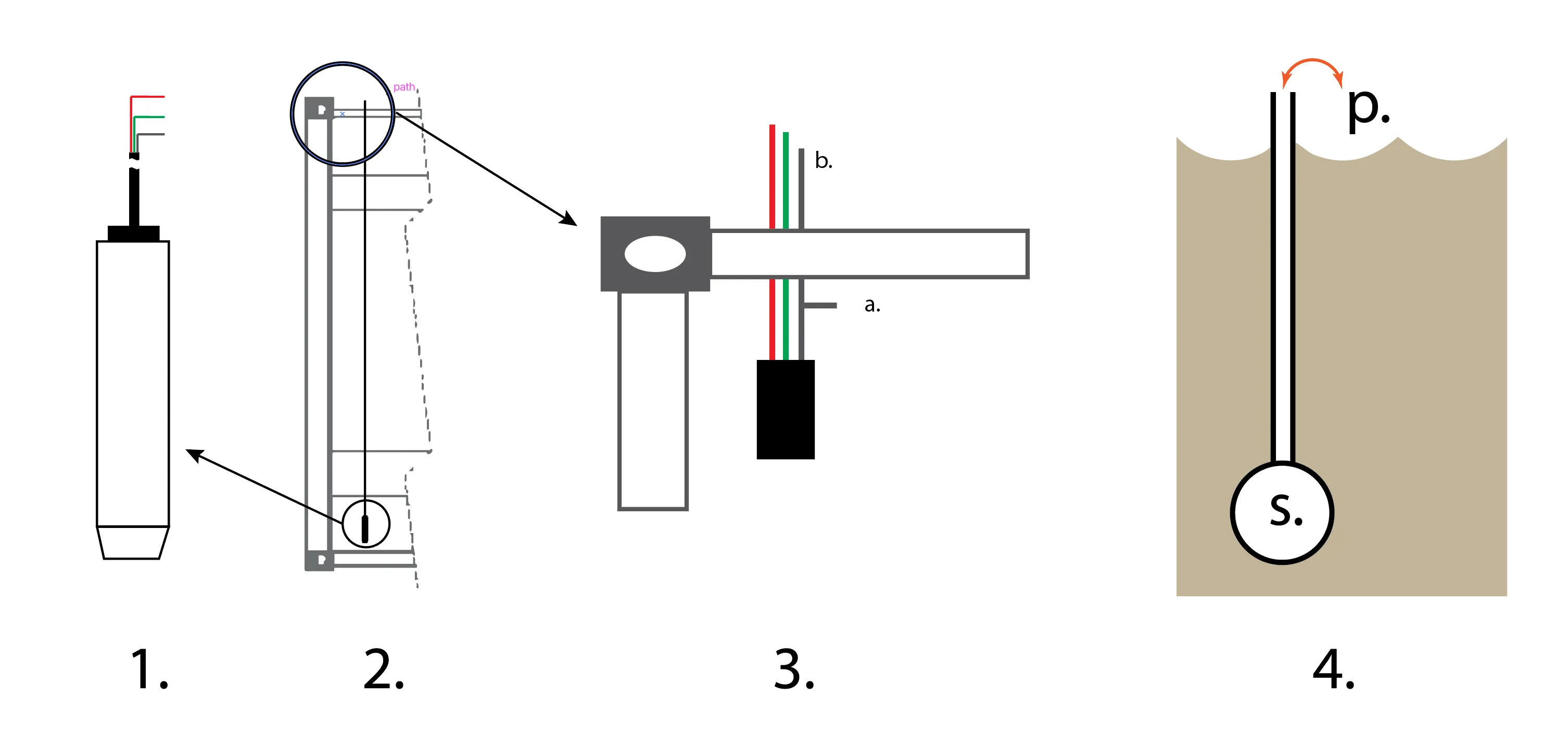
Probe Location
See 1 and 2 in diagram above
- The probe should be submerged in the deepest part of the tank
- The probe will work in both horizontal or vertical orientations
- Avoid water contact at all times
Wiring
See 3 in diagram above
- Ensure the sensor cable exists the tank via a weatherproof sealing
- Do not fold, bend or crimp the cable, as restriction to the air line shall interfere with performance
- Where the sensor vent is located within a junction box, it must be free air vented. Sealed junction boxes can retain pressure/vacuum and restrict the operation and performance of the sensor.
- The vent tube can be retained inside the tank in the air void (a.)
- Alternatively the vent tube shall be open to atmospheric pressure (b.)
Fuel Transfer
- Where high capacity pumps are in use (filling or dispensing) ensure adequate venting is provided at all times.
Sensor venting
See 4 in diagram above
- Ensure the sensor (s.) pressure vent and liquid height can pressure equalize. (p.)
- If the tank is free air vented, without any restriction the sensor can vent to atmosphere
- Where there are filters or breathers installed to the tank its advised to let the vent remain inside the tank
- Ensure the vent tube is protected from weather, water ingress and dirt.
Level Gauge Setup Process
The following steps outline the typical setup process for the Fuellox Level Gauge (LG). Estimated times are provided to assist first-time installers.
-
Probe Installation – 30 minutes
-
Wiring – 15 minutes
-
Prepare Strapping Table – 10 minutes
-
Hardware Configuration – 5 minutes
-
Level Calibration – 15 minutes
-
Notifications & Alerts
-
Reporting
-
Maintenance
-
Other Considerations
1. Probe Installation
Begin by locating a spare port on the top of the tank. A 2” threaded port is preferred, though a 1” port can also be used if necessary.
Drill a hole in the fitting to accommodate a cable gland. Install the gland and feed the sensor cable through it so the sensor can be fully submerged in the fuel.
Apply a suitable sealing compound around the tank fitting to prevent water ingress. Keep the cable gland loose during installation so the fitting can be threaded in place without twisting or damaging the sensor cable.
Once the fitting is reinstalled, lower the sensor until it reaches the bottom of the tank. You should be able to feel or hear the sensor make contact with the tank base.
It is strongly recommended to inspect the tank for water before installing the probe. If water or debris is present at the bottom of the tank, it must be removed prior to installation. Contaminants such as water and dirt can damage the Level Gauge (LG) and impair its functionality.
Make sure the final adjustments are made to the sensor line and cable gland so the probe sits securely at the tank’s bottom. Excess cable can remain inside the tank. If the cable is too short, extend it using a suitable insulated cable compatible with the Fuellox system.
Do not tamper with the black breather line. If it must be terminated in a junction box, a weatherproof breather is required. This line must remain open to free air to equalize pressure inside the sensor tube. Proper venting is critical to maintaining accurate performance and long-term reliability of the LG.
2. Wiring
Connect the red power wire to J17-VBAT and the green sensor wire to J17-4-20mA on the Fuellox board.
| Probe Wire | Description | Fuellox Board | Fuellox DIN |
|---|---|---|---|
| Red | Power | J17-VBAT | 18 – Red Screw In |
| Green | Sensor | J17-4-20mA | 19 – Green Screw In |
| Black Tube | Breather | Open | None |
| Black Wire | Shield, soldered tip | Earth | Earth |
| Other | Not Applicable | N/A | None |
3. Create the Strapping Table
Begin by identifying the Safe Fill Level (SFL) on the tank’s dipstick.
Next, take a series of measurements from the dipstick. For each measurement point, record the liquid height in millimetres (mm) and the corresponding volume in litres (L). This data forms the basis of the strapping table used for accurate fuel level monitoring.
Example Strapping Table
| Liquid Diesel (mm) | Volume Litres (L) |
|---|---|
| 0 | 200 |
| 290 | 5,860 |
| 590 | 7,710 |
| 880 | 9,570 |
| 1180 | 11,430 |
| 1470 | 13,290 |
| 1760 | 15,140 |
| 2060 | 17,000 |
| 2350 | 18,860 |
| 2650 | 20,000 |
Data Points
| Tank Style | Recommendation |
|---|---|
| Cubes, to 1.3m high | 4–5 points is plenty |
| Containerised to 2.7m high | 6–8 points |
| Bullet tanks & Horizontal Cylinders | 15–20 points |
| Vertical tanks > 3m | Alternative probe required |
4. Configuration
Hardware settings are configured via the Fuellox mobile app. This is a one-time setup typically performed during the commissioning of the Level Gauge (LG).
To begin, open the Fuellox app and navigate to the Device Manager.
Proceed to enable the level module using the following steps:
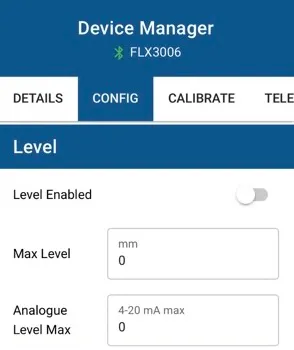
Hardware Settings
| Setting | Value |
|---|---|
| Level Enabled | On |
| *Max Level | 2700 |
| *Analogue Level Max | 20 |
Apply the settings as outlined:
-
Click Save.
-
Wait for the two green confirmation notifications.
-
Power cycle the unit.
5. Level Calibration
Once the Level Gauge (LG) is installed and the strapping chart has been uploaded, the next step is to calibrate the LG. Calibration is often most effective when the tank is full.
To calibrate the unit, contact the Help Desk. Manually perform a tank dip and report both the volume and the measured height in millimetres. This information will be used to align the calibration with the latest data point and make any necessary adjustments.
Data Needed for Calibration
| Data | Reported Value Units |
|---|---|
| Actual Dip Volume | Litres |
| Liquid Height | mm Height |
Once calibration is updated, follow these steps:
-
Sync the Fuellox app to retrieve the updated calibration data.
-
Perform a test dispense to ensure values are updating correctly.
-
Compare the reported tank level with the actual level measured using the dipstick.
In some cases, calibration may require adjustment after the initial attempt.
Over the following days or weeks, periodically verify that the Level Gauge (LG) readings align with manual dipstick measurements. If significant discrepancies are observed, a recalibration should be performed.
6. Notifications & Alerts
Installers and resellers can configure notifications for LG (Level Gauge) customers.
The Fuellox Help Desk can also assist with setting up notifications.
Notification Types
LG notifications can be configured in two ways:
-
Scheduled – Notifications are checked and sent daily at a predefined time.
-
Immediate – Notifications are triggered instantly when the tank level drops below the set point.
Immediate events are one-time alerts. If the SMS or email is missed, no follow-up will be sent. Scheduled notifications, however, repeat daily until the fuel level rises above the set threshold.
Notification Set Points
There are two types of notification thresholds:
-
Warning – Provides advance notice of a low level, allowing you to source updated fuel pricing.
-
Reorder – Indicates it’s time to place a new order with your supplier.
Notifications can be sent via email or SMS. Include multiple team members to ensure alerts are not missed due to absence or staff changes.
You may also configure LG notifications to be sent directly to your fuel supplier to assist with delivery scheduling.
7. Reporting & Access
LG data is available through both the web app and the mobile app.
To provide access, inform the Fuellox Help Desk which team members require visibility and specify whether access should be granted for web, mobile, or both platforms.
8. Maintenance
-
Keep the tank clean and free from water.
-
In high-risk water ingress areas, position the probe above the water layer and recalibrate after repositioning.
-
Inspect the probe periodically in line with routine tank maintenance schedules.
-
Compare actual vs reported tank levels weekly, especially during the first month after installation.
-
If the probe is damaged or data is not updating, notifications may fail to send. It is the customer’s responsibility to ensure the equipment remains operational at all times.
LG Performance Tips
If the LG is not producing accurate data, consider the following steps:
-
Update the strapping chart with additional data points.
-
Verify fuel density with your supplier and report this to the Fuellox Help Desk.
-
Make sure the black breather tube is clear and unobstructed.
-
Recalibrate the LG when the tank is full.
-
Set conservative warning and reorder points.
-
Manually dip the tank occasionally and compare readings.
9. Other Considerations
-
Minor variations in level accuracy are expected due to thermal expansion, seasonal temperature changes, and sensor precision drift.
-
Tanks not installed on perfectly level surfaces may cause discrepancies between the LG readings and manual dipstick results. In such cases, adjust your rounding settings to account for added margin of error.
-
LG-reported levels are intended for delivery scheduling only.
-
The LG is designed for static tank use only. Use in mobile tanks or service trucks may lead to inaccurate or inconsistent readings.
-
The LG is not suitable for hazardous fuels such as ULP or aviation fuels.
-
Use of the LG is at the customer’s own risk.