Installation Guide
The Fuellox Bowser is an all-in-one, ready-to-use fuel dispensing solution that requires minimal setup. Prewired and calibrated, it ensures quick and reliable integration into the Fuellox system. With multiple installation options available, the process is streamlined for efficiency, making setup simple and effortless.
The Fuellox V2 Bowser includes the following components:
- 6m Hose and Swivel
- Auto shut-off nozzle
- 60 LPM Pump
- Precision pulse meter
- Integrated Nozzle Switch
- Integrated Emergency Stop (e-stop)
- 240V AC Power Lead
- Fuellox Fuel Management System
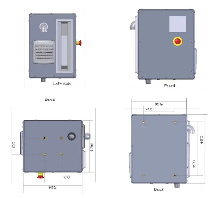
- The system is housed in a powder-coated alloy enclosure with dimensions:
- Height: 450mm,
- Width: 356mm,
- Depth: 371±1mm.

Specifications
| Item | Specification |
|---|---|
| Enclosure | Dimensions subject to change. Check the latest data sheet and drawings for your actual unit. Height: 45cm Width: 41cm Depth: 32cm. Measurements exclude protrusions such as fittings and vents. IP 55 or better |
| Weight | Approx 25 kg total mass |
| Shipping | Small pallet includes hose, nozzle etc. |
| Hose & Nozzle | 4m x 25mm heavy duty high-quality hose with swivel and auto shut off nozzle. Optional: 6m hose or No Hose |
| Pump | Standard pump is 80 lpm. Options for 40, 56, or 100 lpm |
| Power | 240V AC Power. Active, Neutral, Earth on covered din rail. Recommend connection to RCD circuit by trade to meet AS1940 or connect a standard lead - excl. |
| Material | Powder Coated Aluminium |
| Mounting | Surface Mount via Base or Rear Hole M10 |
| Terminals | Internal Din Rail. Power input. 4-20 mA level sensor (optional accessory) |
| Power | Short - 12 or 24V DC. Long - 240V AC |
| Frequency MHz | 2.4 GHz |
| Approvals | AS/NZS CISPR 32:2015 + AS/NZS 4268:2017 |
| BLE | Recommended External Antenna sold separately |
| Inputs | NA |
| Nozzle Switch | Included |
| E Stop | Included |
| Bypass Mode | Optional. Request at time of ordering |
| Pump Shut Off | Pump shut off on duty cycle timer |
| Pulse Meter | High quality Hall Effect by Flomec |
| Certifications | AS/NZS CISPR 32:2015 + AS/NZS 4268:2017 |
| Operating Conditions | -10°C to 40°C |
| Warranty | 12 Months from delivery. Extended warranty options available |
| Installation | See installation directions |
| Configurations | Bypass. Flow Rate: 40, 56, 80 or 100 lpm |
Bowser Installation Setup
To properly install the Fuellox Bowser product, the following modules and accessories must be configured:
- Mounting Setup
- Inlet Configuration
- Power Supply
- Electrical Compliance
- Perform Calibration
- Maintenance and Service
Let’s discuss each step to understand their features in detail:
1. Mounting Setup
The Fuellox Bowser can be installed in two ways—
- Base Mounting
- Rear Mounting
The details for each mounting type are as follows:
Base Mounting
Base Mounting involves securing the unit directly to the ground or a flat surface for stable installation.
To achieve this setup, follow the steps below:
- Required holes: Drill 4x Mx holes arranged in a 100mm x 100mm square pattern to secure the unit.
- Fixtures: Use Mx screws to firmly attach the unit to the ground or flat surface, ensuring stability.
Rear Mounting
Rear Mounting involves attaching the unit to a wall or adjacent structure for a secure and space-saving installation.
To achieve this setup, follow the steps below:
- Required holes: Drill 4x Mx holes in a 200mm W (width) x 350mm H (height) pattern on the wall or adjacent structure for secure attachment.
- Fixtures: Use Mx screws to securely fasten the unit to the wall or structure, ensuring it is properly aligned and stable.
In addition to these mounting methods, you can also mount the unit using a pedestal, which allows it to be securely placed on a concrete pad.
It looks like the error is caused by the <br> tag in the markdown. For proper syntax in markdown, the line breaks within the table need to be handled differently. You can remove the <br> tags and use proper formatting.
| Base Mounting | Rear Mounting | |
|---|---|---|
| Definition | Secures the unit directly to the ground or flat surface for stability. To achieve this setup, follow the steps below: | Attaches the unit to a wall or adjacent structure for space-saving. To achieve this setup, follow the steps below: |
| Required holes | Drill 4x Mx holes (100mm x 100mm pattern). | Drill 4x Mx holes (200mm W x 350mm H pattern). |
| Fixtures | Use Mx screws to secure the unit to the ground or flat surface. | Use Mx screws to securely fasten the unit to the wall or structure. |
| Alternative mounting | Option to use a pedestal for securing the unit on a concrete pad. | Option to use a pedestal for securing the unit on a concrete pad. |
This should now work without throwing errors in your markdown.
You can view the full dimensions and component of the Bowser unit by accessing the technical sheet here.
2. Inlet Configuration
The inlet connection plays a critical role in ensuring that the fuel system operates effectively. For the Fuellox Bowser, it is essential to use the correct components to ensure a secure and reliable fuel transfer process.
The first step is to install a heavy-duty 1” BSP suction hose or spear. It is crucial to specify a suction hose, as other types of hoses may collapse under the suction pressure created by the pump. This could lead to a malfunction or disruption in fuel transfer.
Alternatively, you can use a steel spear with a 1” BSP thread, which is designed to ensure a secure fit and allow for efficient fuel transfer.
Additionally, it is recommended to apply a thread sealing compound for a better seal. Follow the product instructions carefully, and make sure to allow the sealing compound to dry before it comes into contact with fuel. This ensures a secure and leak-free connection.
For sealing, you can use Loxeal 58-11, a high-quality thread sealant that is available at most Bunnings Stores. It is essential to use a suitable thread sealing compound to ensure a leak-proof connection and avoid any fuel spillage.
You can purchase the recommended thread sealing compound, Loxeal 58-11, from Bunnings Store. Click here to buy.

Installing the Swivel Fitting at the Pump Inlet
If a Bowser system needs to be installed with a suction spear, it is recommended to use a swivel fitting at the pump inlet. A suitable fitting for this purpose is available from Ryco, part number S80-16-16. The last column of the table provides details of the suitable swivel fitting options, such as Ryco part number S80-16-16 for different thread sizes and dash sizes, ensuring compatibility with the Bowser system.
As shown in the table, the correct part number for the swivel fitting is essential for the proper installation. You can identify the fitting based on the required thread size and dash size.
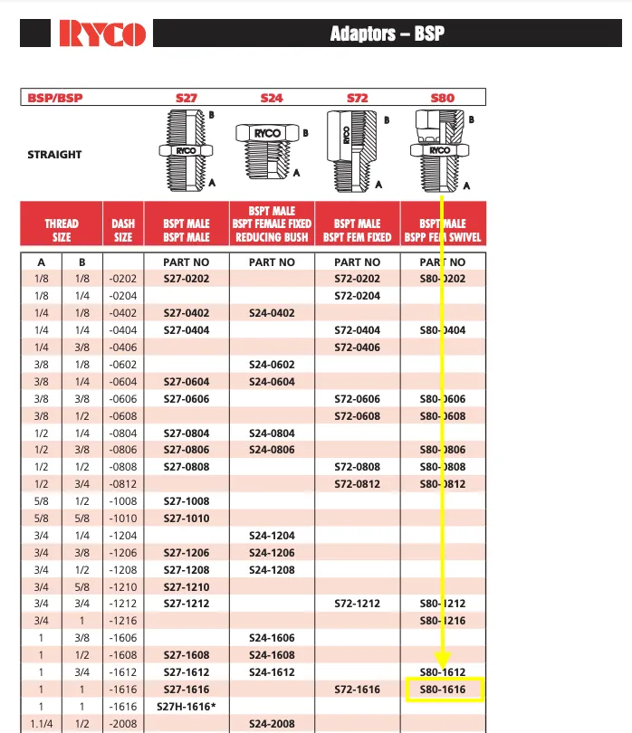
Once you have identified the correct part number, install the swivel fitting onto the inlet. Ensure that the pump is positioned correctly, and secure the inlet using an appropriate thread sealant.
3. Power Supply
The Fuellox Bowser unit is supplied with a 2-meter cable that is left unterminated. An electrician will need to connect this cable to a circuit and ensure that the following electrical requirements are met for proper installation:
- IP68 Enclosure: Ensure the enclosure is IP68 rated for weatherproofing and durability.
- Mains Isolator: A lockable isolator should be installed to disconnect the mains supply for safety purposes.
- RCD Protection: Ensure a residual current device (RCD) is included for protection against electric shock.
- Earth Stake: If an earth stake is not already in place, it must be installed for proper grounding.
In cases where a captured appliance inlet is needed, ensure it meets the specific electrical compliance requirements for your installation site.
Finally, remember to allow thread sealants to dry fully and double-check all connections, both inside and outside, before commissioning the system and handing it over to the client.
4. Electrical Compliance
To ensure the Bowser system is fully compliant with electrical standards, it must be installed according to AS3000. Depending on the zoning and the site’s electrical requirements, a dedicated supply and RCD (Residual Current Device) may be necessary. It is crucial to consult a qualified electrician to evaluate your specific needs and determine the appropriate setup for your installation.
Note: Ensure electrical cables are positioned safely to avoid trip and vehicle hazards. Follow proper cable management practices to prevent accidents and damage.
The Electrical Compliance has the following components:
- Mark I Bowser
- Mark II Bowser
Let’s discuss these in detail:
Mark I Bowser
Content for the Mark I Bowser is coming soon. Please contact the help desk for further assistance and information.
Mark II Bowser
The Mark II Bowser features a separate access panel for electrical connection, providing a more organized and secure setup. This panel allows easy connection of the main power supply and level input for the Bowser system, as shown in the image. The main power and level input connections are clearly labeled for a seamless installation process.
Key features for installation and safety include:
- Mains Power Connection: Ensure correct wiring for the 240V AC input.
- Level Input: Properly connect the level sender to monitor fuel levels accurately.
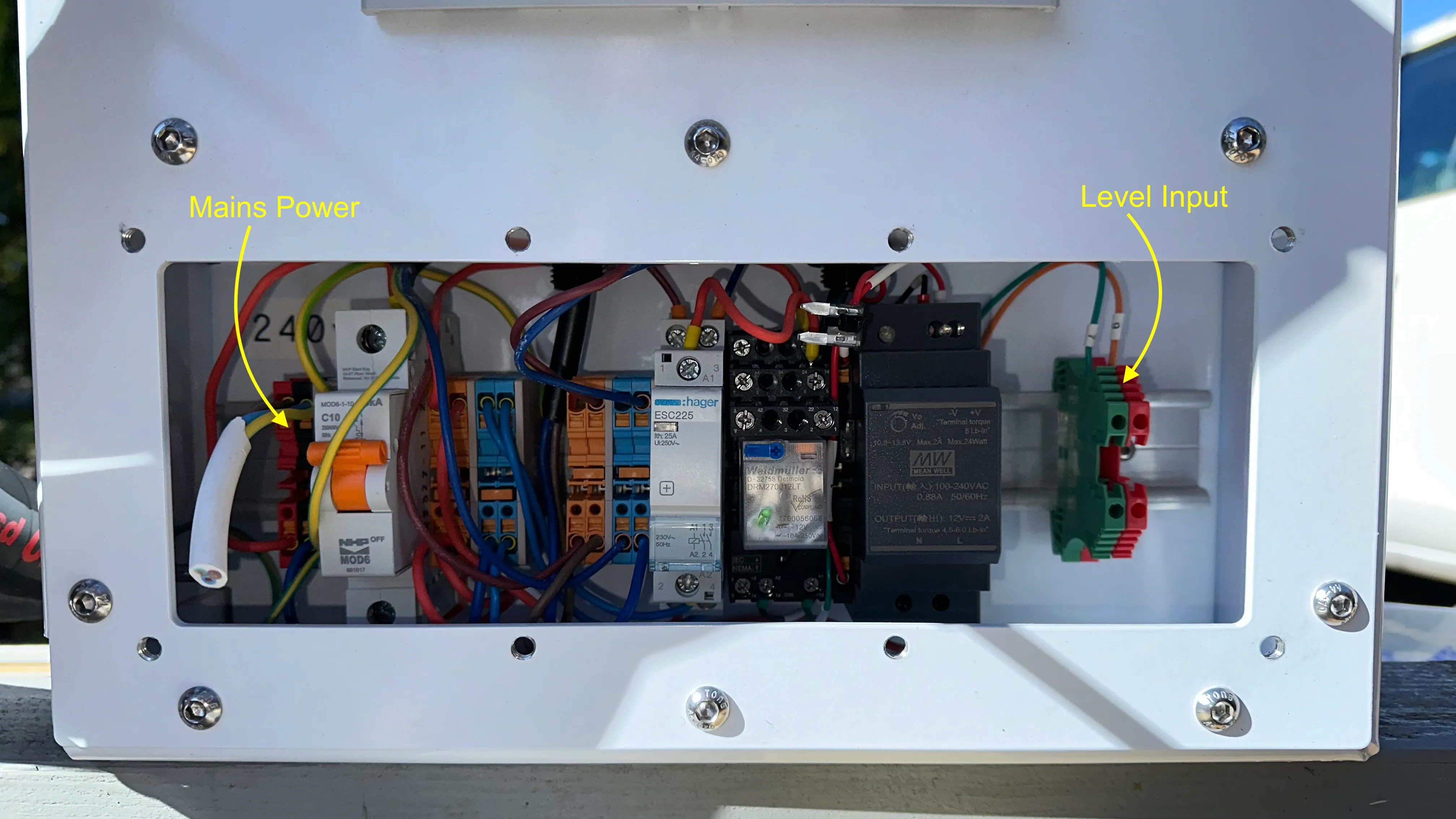
Make sure to insert the appropriate holes and glands for both the mains power and the level sender in a suitable location to facilitate proper installation.
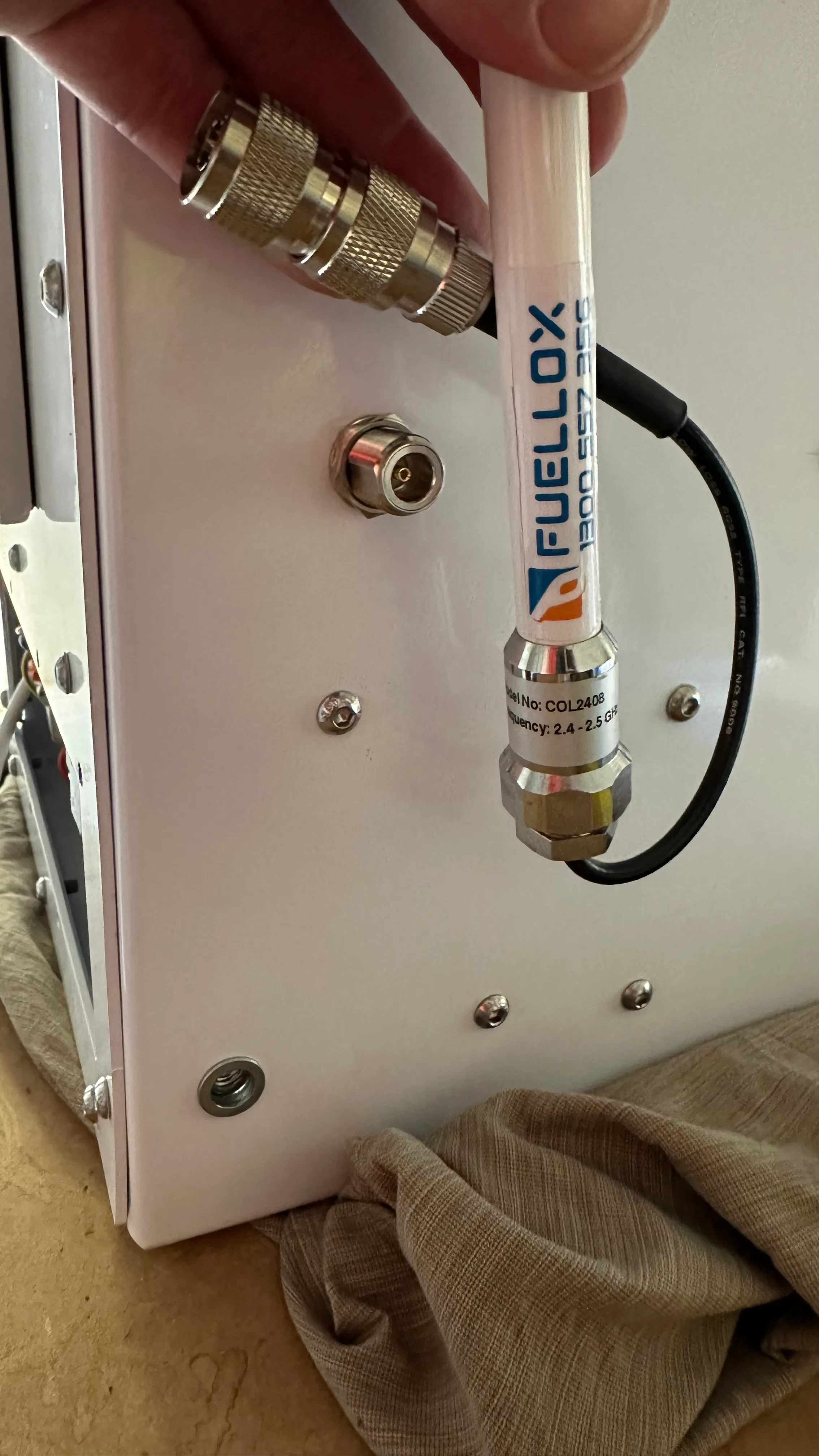
The rear antenna port should be connected to the antenna for optimal and reliable performance. Ensure the extension cable is properly connected, and mount the antenna at a high point, well outside any bunded area. Antenna mounts are provided to facilitate the installation.
Verify the system is operating reliably before closing the access panel. Also, make sure the isolator switch remains in the ON position for proper functioning.
5. Perform Calibration
Calibration is an essential step for ensuring that your Fuellox Bowser provides accurate readings. Each Fuellox Bowser is equipped with a high-performance meter that is pre-calibrated at the factory to ensure precise measurements. These meters come with a calibration certificate, and the calibration values are set directly in the factory, providing reliable performance from the moment the unit is installed.
It is important to keep in mind that while the Bowser is calibrated during production, any further calibration or adjustments should only be carried out by a qualified, licensed contractor. This ensures the system remains accurate and operates according to industry standards. Always ensure that calibration is done by experienced professionals for the best results.
6. Maintenance and Service
For proper installation, service, and support, a wiring guide is provided. Always consult the Fuellox Help Desk before performing any service or maintenance on the mini Bowser to ensure correct procedures and safety protocols are followed.
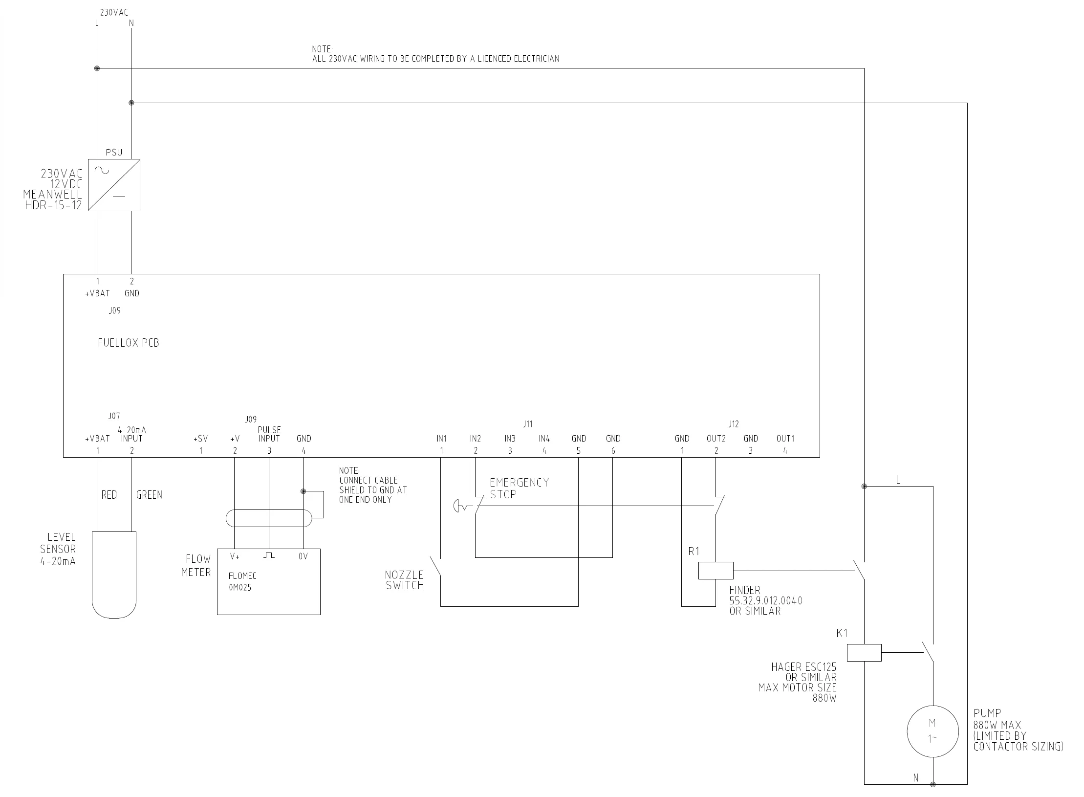
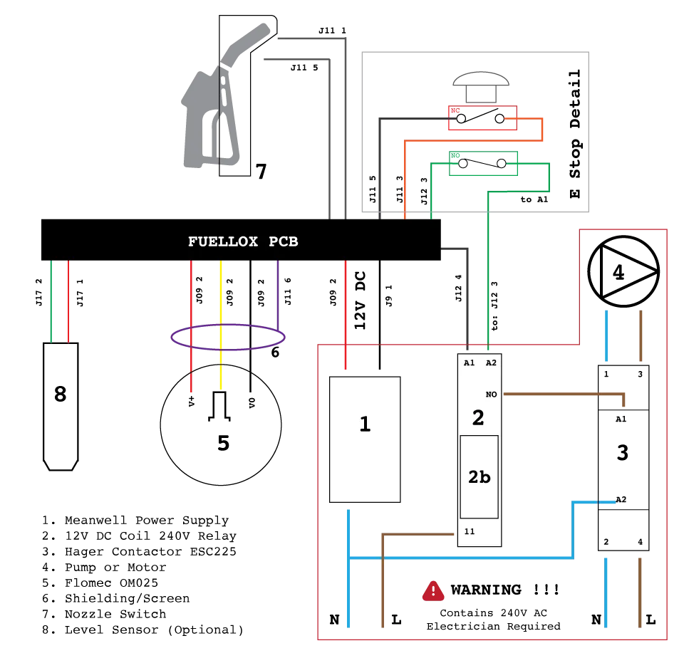
Working of an Electrical Diagram
The electrical diagram shown provides a detailed layout of the wiring and connections for the Fuellox Bowser. It is crucial to follow this diagram for service work to ensure proper functionality and safety.
Here’s how it works:
1. Power Supply: The diagram starts with the 230V AC input, connected to the Meanwell Power Supply (1). This supply powers the entire system.
2. Relay and Motor Control: A 12V DC Coil 240V Relay (2) is connected to the system, which controls the flow of electricity to the pump or motor (4). The Hager Contactor ESC225 (3) allows the relay to control the flow of electricity safely.
3. Flow Meter and Level Sensor: The Flomec OM025 Flow Meter (5) is connected to detect the flow of fuel. Additionally, the Level Sensor (8) helps in monitoring the level of fuel in the system.
4. Emergency Stop: The Emergency Stop (6), indicated in the diagram, is wired to shut down the system when necessary, ensuring safety.
5. Output Connections: The nozzle switch (7) is connected to the system to control fuel dispensing. The diagram also shows output terminals (J12) for controlling external devices, ensuring proper operation of the fuel pump and other system parts.
6. Safety Warning: A prominent safety warning is displayed in the diagram about the 240V AC system, emphasizing that all work involving 240V must be handled by a licensed electrician.
Engineering Diagram
The diagram provided is the electrical schematic for the Fuellox Bowser system. Here is a short breakdown of its components and their function:
1. Power Supply (PSU): The system is powered by a 230V AC input, which is supplied to the PCB (Printed Circuit Board) for operation.
2. Level Sensor: The level sensor monitors fuel levels, sending a signal to the system for further action.
3. Flow Meter: The flow meter, represented as FLOMEC OM025, measures the fuel flow in the system, which is important for accurate dispensing.
4. Nozzle Switch: A safety feature that ensures the nozzle is activated only when necessary.
5. Emergency Stop: An emergency stop button is included for manual control to halt the system in case of any safety issues.
6. Motor: The pump motor is responsible for moving the fuel, with a maximum motor size limit of 880W (controlled by the contactor sizing).
7. RCD Protection: This setup may require RCD (Residual Current Device) protection for electrical safety.
8. Relay (R1): The relay controls the electrical signal flow, ensuring the system operates as intended.
9. Antennas & Communication: The system includes a communication component that connects via the rear antenna port, ensuring reliable operation when connected.
Note: Ensure proper cable shielding, connecting the shield to ground at one end only.