
Installation Guide
The Fuellox Facia is ideal for installations where the electronics are placed inside an enclosure, with the user interface accessible externally.
Recommended Installation Locations:
- Mounted on Electrical Cabinets
- Integrated into Container Doors or Side Panels
Structure & Key Components
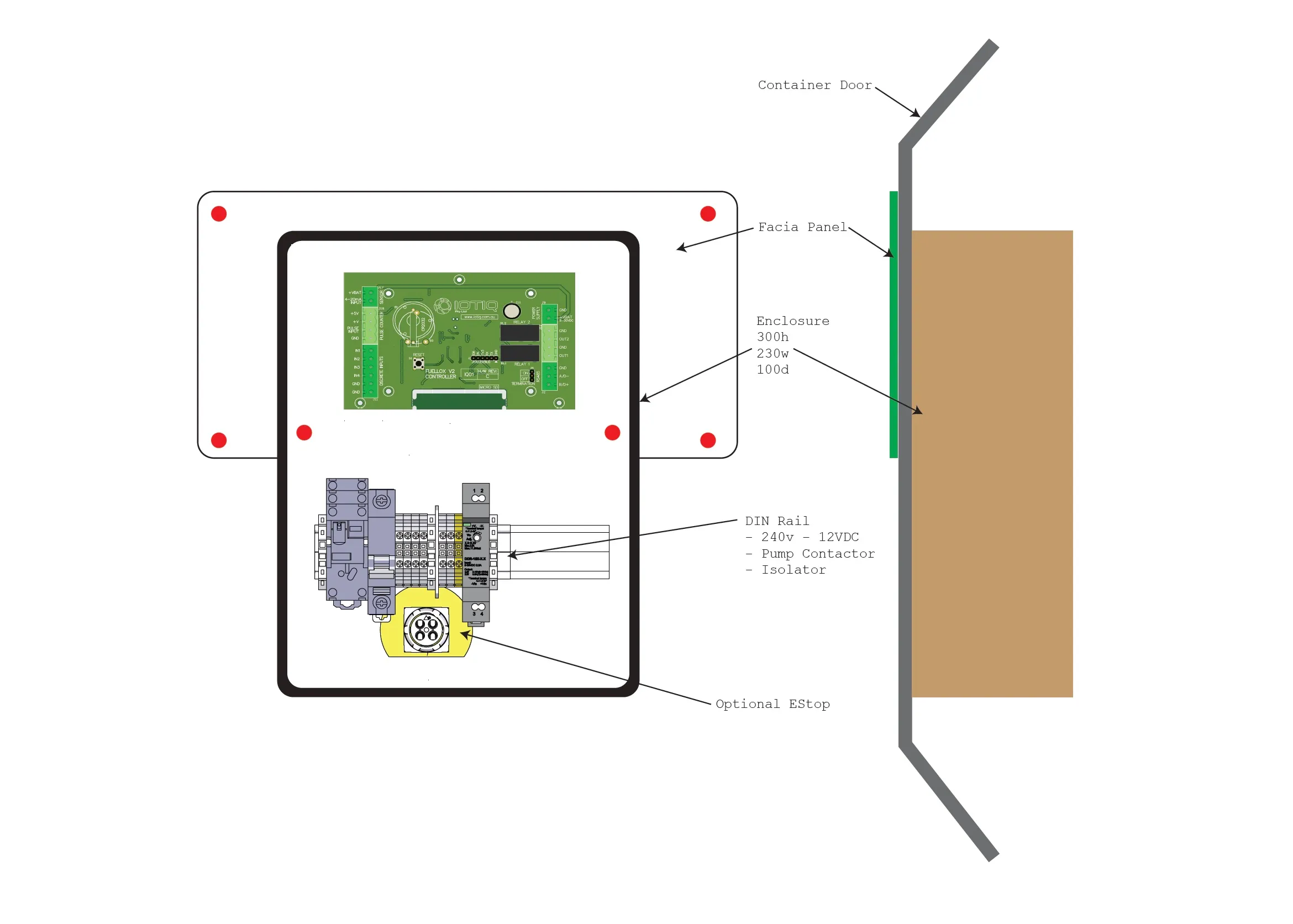
The Facia structural diagram illustrates the installation setup, showing the facia panel mounted on a container door with enclosed electronics, a DIN rail, and an optional emergency stop.
The Facia consists of key components that ensure efficient functionality and secure installation. Below are its main aspects:
-
Facia Front
-
Facia Inside
-
Main Elements
Let’s explore them in detail:
Facia Front
The external interface designed for user interaction and accessibility.

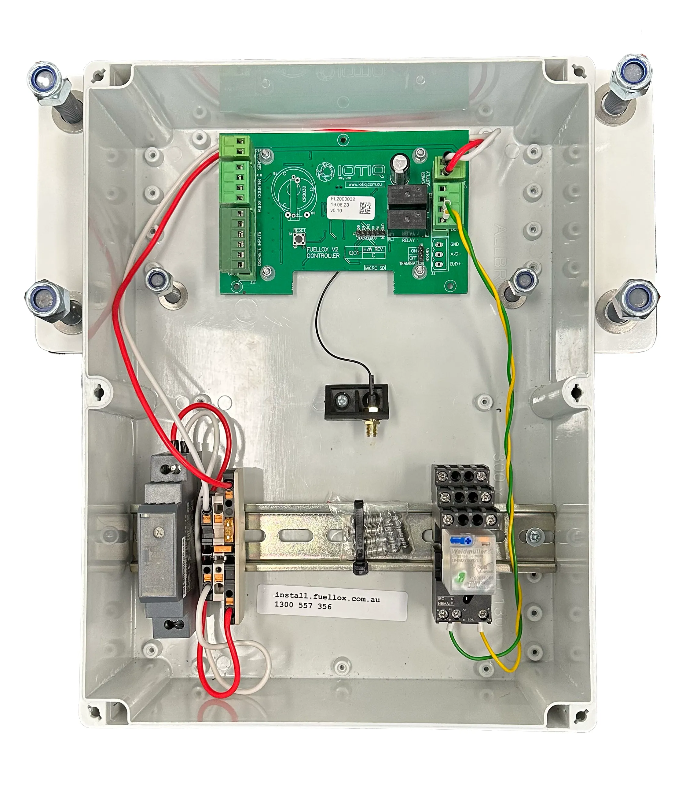
Facia Inside
The enclosed section housing essential electronics and control components.
Simplified version displayed: This unit does not include a 240V AC provision.
Main Elements
Critical components such as the facia panel, DIN rail, pump contactor, isolator, and optional emergency stop (E-Stop).
| Part | Description |
|---|---|
| PCB | Fuellox PCB |
| Power Supply | Meanwell 240V to 12V DC Power Supply + Connectors and fuse |
| Relay | 2-channel relay with 12V DC Coil |
| BLE | Bluetooth Aerial connector |
Installation Steps
1. Preparation
Place the template on the surface where the Fuellox Facia will be mounted.
Make sure that you have the correct template and verify that the hole sizes align with the studs on your components.
Template A3
The diagram shown provides precise measurements for mounting the Fuellox Facia, ensuring accurate hole alignment.
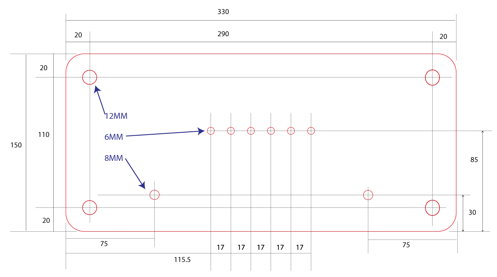
For accurate installation, download and print the mounting template on A3 paper PDF Template for Download – Print on A3.
2. Mounting
- Secure the facia panel to the tank using a silicone-based sealant.
- Fasten the four main studs with appropriate washers and Nylex nuts.
- Install the Mobile Enclosure onto the mounting studs and secure it firmly using washers and Nylex nuts.
3. Wiring
The Fuellox Facia operates exclusively on a 240V AC power supply.
Wiring has the following Power Variants:
- 12V DC Systems
- 240V AC Systems
These are discussed as follows:
12V DC Systems
For detailed installation instructions, refer to the 12V DC wiring guide.
240V AC Systems
For detailed installation instructions, refer to the 240V AC wiring guide.
4. Aerial
Refer to the Remote BLE Aerial Installation Guidelines for detailed instructions.
5. Facia Din Expanded
The Expanded DIN option for Fuellox Facia provides:
- 240V AC Power supply
- 240V AC Pump contactor
- BLE Antenna Connector
- IO Inputs for
- Nozzle switch
- Dual Channel NO/NC Estop
- Nozzle switch
- Level instrument
Scan the QR Code to access this manual section on a mobile device.

The Facia DIN Expanded section provides details on its internal structure and wiring specifications.
- Facia - Expanded DIN (Internal)
- Facia - Expanded DIN Wiring
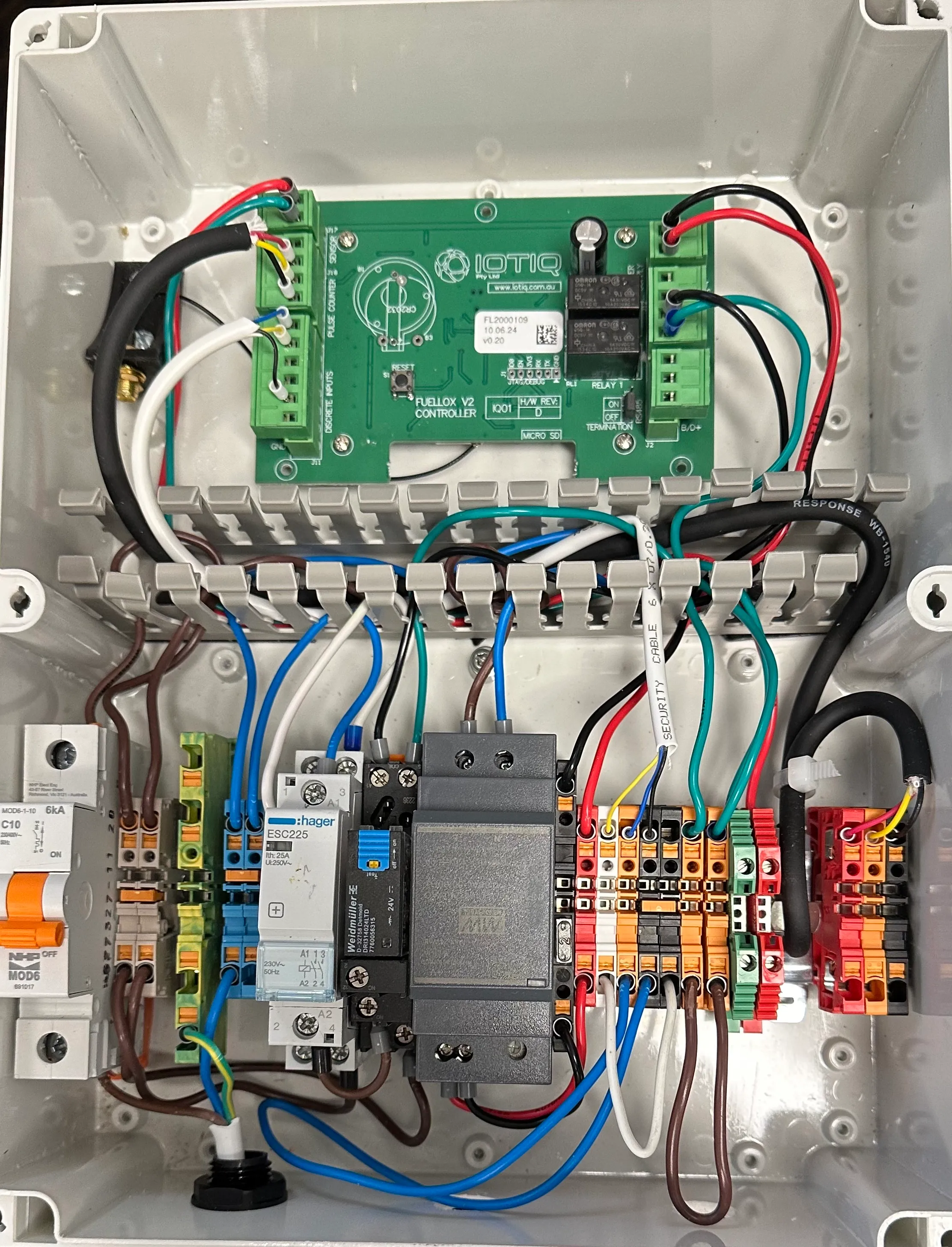
Facia - Expanded DIN (Internal)
Displays 240V AC provision along with the I/O section.
Facia - Expanded DIN Wiring
Covers the detailed wiring layout and connections for proper installation.
5.1 Installation of Facia Din Expanded
A qualified electrician must perform the installation of 240V systems. The warranty will be void if the installation is carried out by an unqualified individual.
Parts Detail
Carefully review the installation drawing and details before proceeding with the installation.
Required Parts:
- Main Isolator
- Dual Channel E-Stop (Normally Open + Normally Closed)
- Nozzle Switch
- Hall Effect or Reed Flow Meter
- 240V AC Pump
- M6 Stainless Nylex Nuts and Washers (x6)
- Outdoor-Grade Silicone for Waterproofing
a. Mount the Facia Panel
- Using the Facia Template, drill the required holes and mount the facia panel. Make sure the correct hole size (6mm or 12mm) for the mounting studs based on your variant.
- Apply silicone to the rear face of the facia panel and mount it on a clean and dry surface.
- Secure the four perimeter mounting studs to the tank.
- Attach the facia enclosure to the inner mounting studs.
- Tighten all six nuts securely.
b. Install the Antenna
- Install the Fuellox Antenna in a high location with minimal interference to the refueling area. Ensure a direct line of sight for optimal performance.
- Make sure the cable is not twisted, crimped, or damaged.
- Do not cut or shorten the cable under any circumstances
- Route the cable through a suitable gland, ensuring that any holes are in a weather-shielded location.
- Avoid creating a water ingress path when installing the antenna cable.
c. Install Dispensing Equipment
- Install and mount the pump, flow meter, pipework hoses, and nozzle.
- Perform a pressure test to confirm the proper operation of the pumping equipment.
- Fit and mount the nozzle switch in a convenient position for the refueling operation.
- It is recommended to place the Fuellox Facia and nozzle switch in close proximity, ideally on the same face of the bund door or wall for ease of use.
d. Hook-Up Process
- Connect the mains supply from the local isolator switch.
- Connect the pump power to the Fuellox according to the wiring schedule.
- Use a suitable shielded cable to connect the flow meter.
- Wire in the E-Stop and nozzle switch.
- Connect the level probe.
- Make sure that any bund penetrations are made in a dry area to prevent water ingress.
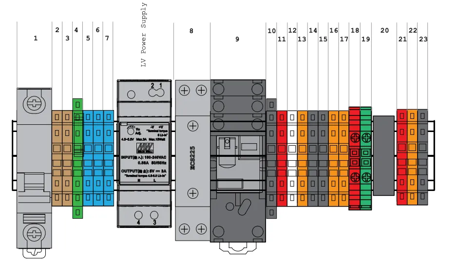
d. Wiring Guide
240V AC Wiring Details
| Number | Block Colour | Description | Connection | Notes |
|---|---|---|---|---|
| 1 | Grey Switch | Isolator Switch Power Isolator, Load | Main Load Supply | |
| 2 | Fawn | Load Distribution Bridged | Main Load Supply | |
| 3 | Fawn | Load Distribution Bridged | Main Load Supply | |
| 4 | Green/Gold | Main + Pump Earth | Main + Pump Earth | |
| 5 | Blue | Neutral Bridged | Main Neutral | |
| 6 | Blue | Neutral Bridged | Pump Neutral | |
| 7 | Fawn | Pump Switched Active | Pump Load | |
| 12v | Dark Grey | Meanwell DC Power Supply | 240V Supply | Powers PCB, motors, etc. |
| 8 | Grey Contactor | Hager ECS225 | 240V Supply | |
| 9 | Black | Relay (1 to 4 poles) depends on product | Connection varies | Consumable Parts via To Pacific |
| 10 | Black - Fused 1amp | 12V DC Ground | 12V 0V | |
| 11 | Red | 12V DC Supply | 12V supply | |
| 12 | White | Low Voltage Nozzle Active | Fuellox IO | |
| 13 | Orange | Normally Open EStop | Fuellox IO | |
| 14 | Black | Nozzle 0V | Fuellox IO | |
| 15 | Black | Normally Open EStop 0V | Fuellox IO | |
| 16 | Orange | Normally Close EStop Loop | Relay Active | |
| 17 | Orange | Normally Close EStop Loop | Relay Active | |
| 18 | Red Screwed | Level Instrument Supply 4-20mA | Fuellox 4-20mA Vcc | |
| 19 | Green Screwed | Level Instrument Sensor 4-20mA | Fuellox 4-20mA Vcc 0V | |
| 20 | Shield Ground | Shielding Ground & Strain Relief | - | |
| 21 | Red | Flow Meter Supply VCC | Hall Supply | |
| 22 | Orange | Flow Meter Sensor | Hall/Reed Sensor | |
| 23 | Black | Flow Meter 0V | Hall/Reed 0V |
d. Wiring Directions
-
Connect mains supply to
- 1 - Load
- 4 - Earth
- 5 - Neutral
-
Connect pump to
- 7 - Pump Active
- 4 - Pump Earth
- 6 - Pump Neutral
-
Connect Nozzle Switch to
- 13 - IO +ve
- 14 - IO ground
-
Connect Dual Channel Estop to
- 12 - Normally Open contact VCC
- 15 - Normally Open contact 0V
- 16 - Normally Closed contact
- 17 - Normally Closed contact
-
Connect Flow Meter
- 21 - VCC, Hall Effect ONLY. DO NOT CONNECT WITH REED FLOW METERS
- 22 - Flow Sensor
- 23 - 0V
e. Power
6. Facia Enclosure
The Fuellox Facia enclosure is a Poly Carbonate enclosure. This part can be ordered or sourced commercially.
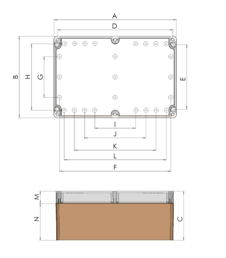
Dimensional Specifications:
| Dimension | Value (mm) |
|---|---|
| A (Height) | 300 |
| B (Width) | 230 |
| C (Depth) | 100 |
| D | 286 |
| E | 196 |
| F | 278 |
| G | 150 |
| H | 200 |
| I | 140 |
| J | 180 |
| K | 220 |
| L | 260 |
| M | 25 |
| N | 75 |
DIN Rails
The is equipped with standard 35mm DIN rails, ensuring compatibility with industry-standard mounting systems.
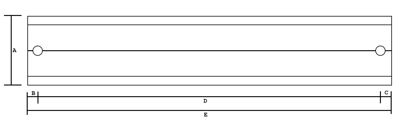
Dimensional Specifications
| Dimension | Long Side (L) (mm) | Short Side (S) (mm) |
|---|---|---|
| A (Height) | 35 | 35 |
| B | 6 | 10 |
| C | 6 | 10 |
| D | 278 | 200 |
| E (Length) | 290 | 220 |