
HD Variants
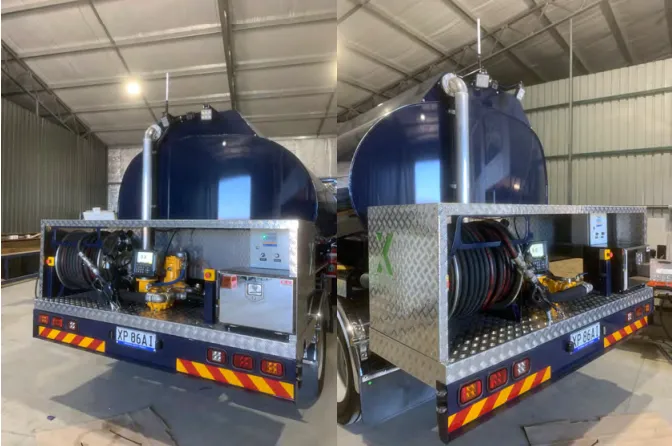
Fuellox HD (Heavy Duty) is a rigid and versatile fuel management system designed for heavy-duty applications, ideal for high-usage environments such as service trucks, large trailers, and areas with limited weather protection. The Fuellox HD is built to handle tough conditions, with a strong steel enclosure and multiple variants to meet specific needs.
Capabilities
Following are the capabilities of the Heavy Duty:
- Setup and calibration through a mobile app for ease of use.
- No SIM cards or FOBs required for operation.
- Over-the-air firmware updates for long-term support and performance improvements.
- Optional interface for Level, Emergency Stop (Estop), Bypass, Nozzle Switch, and more functionalities.
Compatibility
Following are the compatibilities of the Heavy Duty:
- Operates on 12V or 24V DC vehicle mains, or an optional 240V AC power source.
- Compatible with both 2-wire Reed and 3-wire Hall Effect pulse meters.
- Supports a wide range of electrical, pneumatic, or hydraulic pumps.
- Comprehensive catalog of wiring instructions available upon request.
- Recommended to use Fuellox High Gain BLE Antenna for optimal performance.
Fuellox HD Variants
Fuellox Heavy Duty comes in several variants to meet different needs. Below are the available options:
- Fuellox HD
- Fuellox HD CLS
- Fuellox HD Custom (LCR meters)
- Fuellox HD (DFV Meter)
Let’s understand each variant in detail:
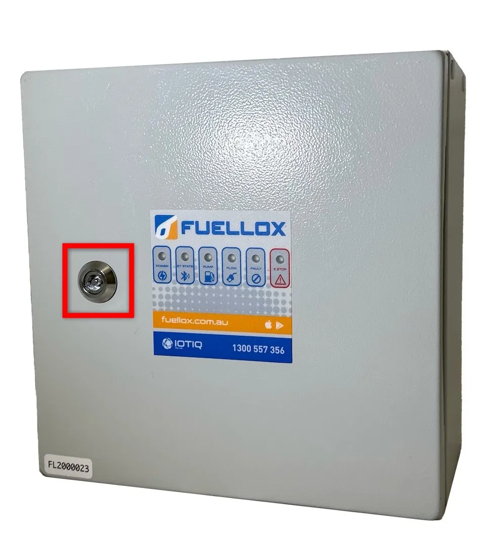
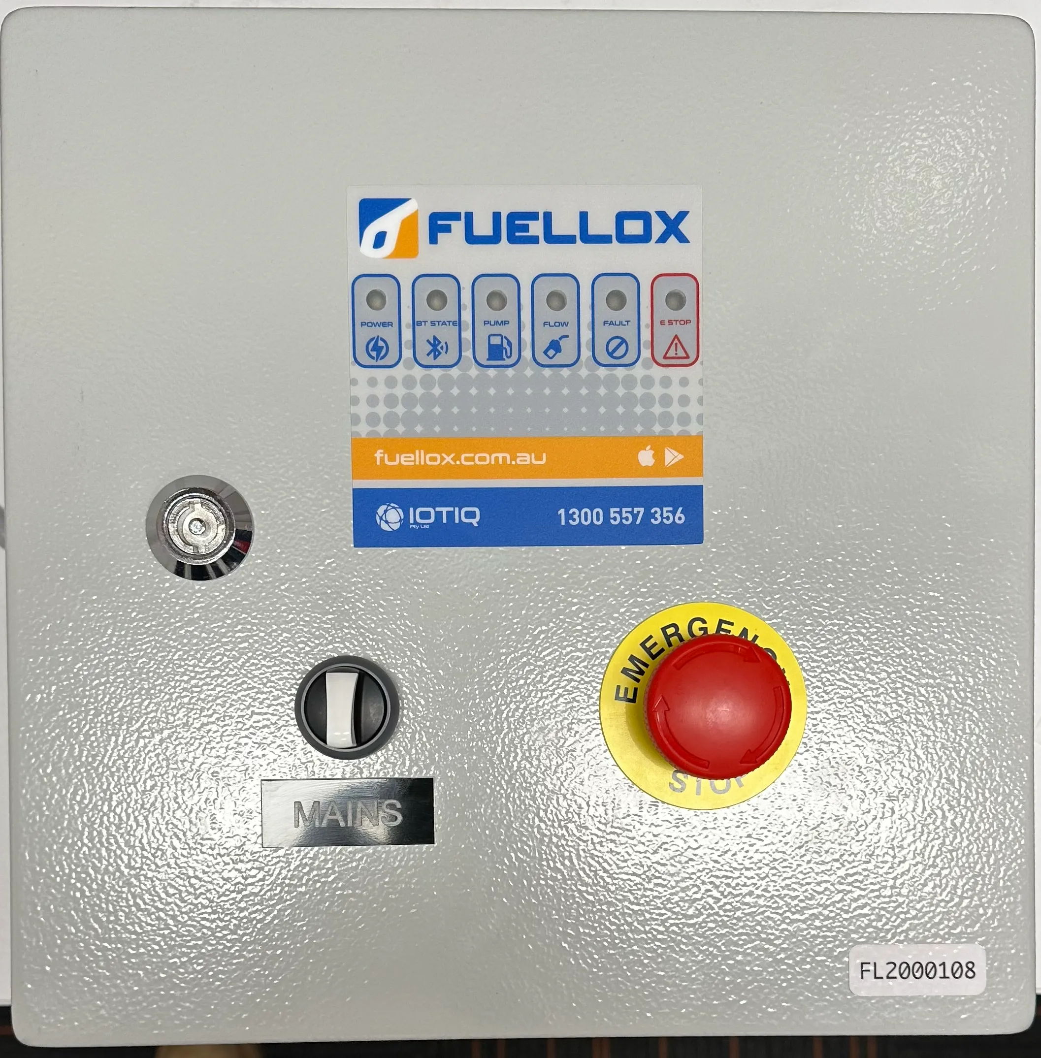
1. Fuellox HD
The standard Fuellox HD is housed in a robust steel enclosure measuring 300mm x 300mm with a typical depth of 200mm, although a 150mm depth option is available.
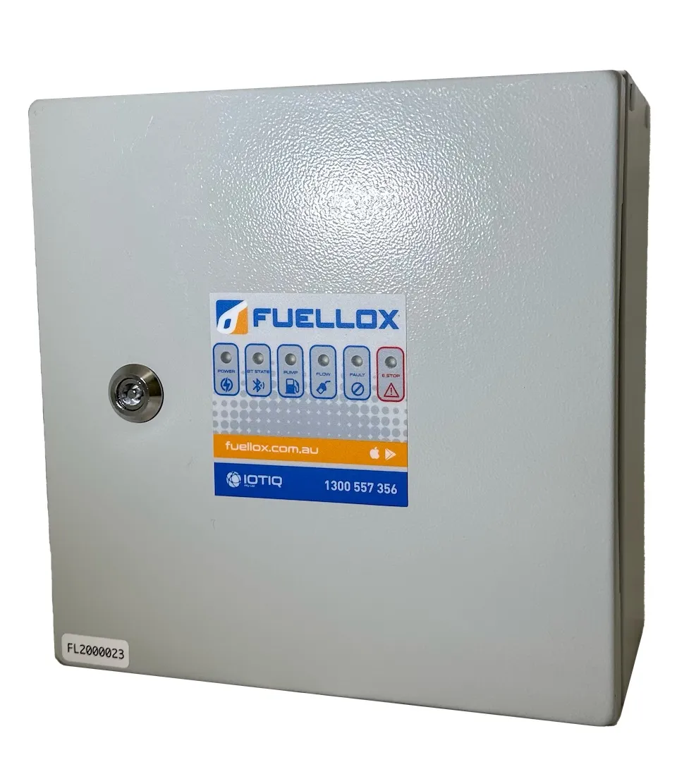
Controls:
- Key Lock: Secures the system to prevent unauthorized access and ensures only authorized personnel can operate the unit.
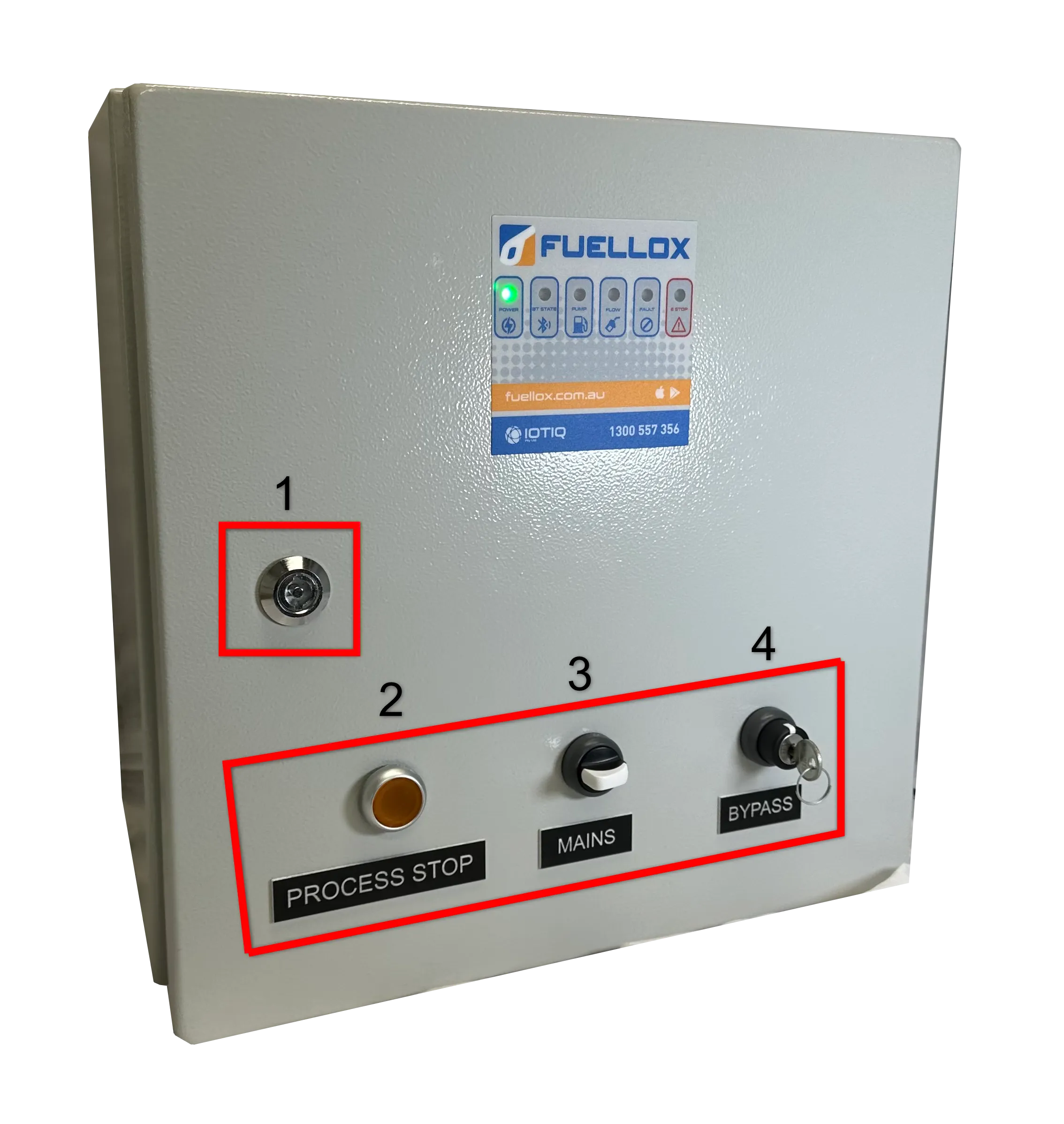
2. Fuellox HD CLS
The Fuellox HD CLS variant is equipped with additional control features and is housed in a 400 x 400 mm cabinet with a 200 mm depth.
The key additional controls include:
- Capture Key
- Emergency Stop/Process Stop
- Mains Power
- Secure Bypass
In this variant, the Emergency Stop (E-Stop) is replaced with an illuminated Process Stop for enhanced visibility.
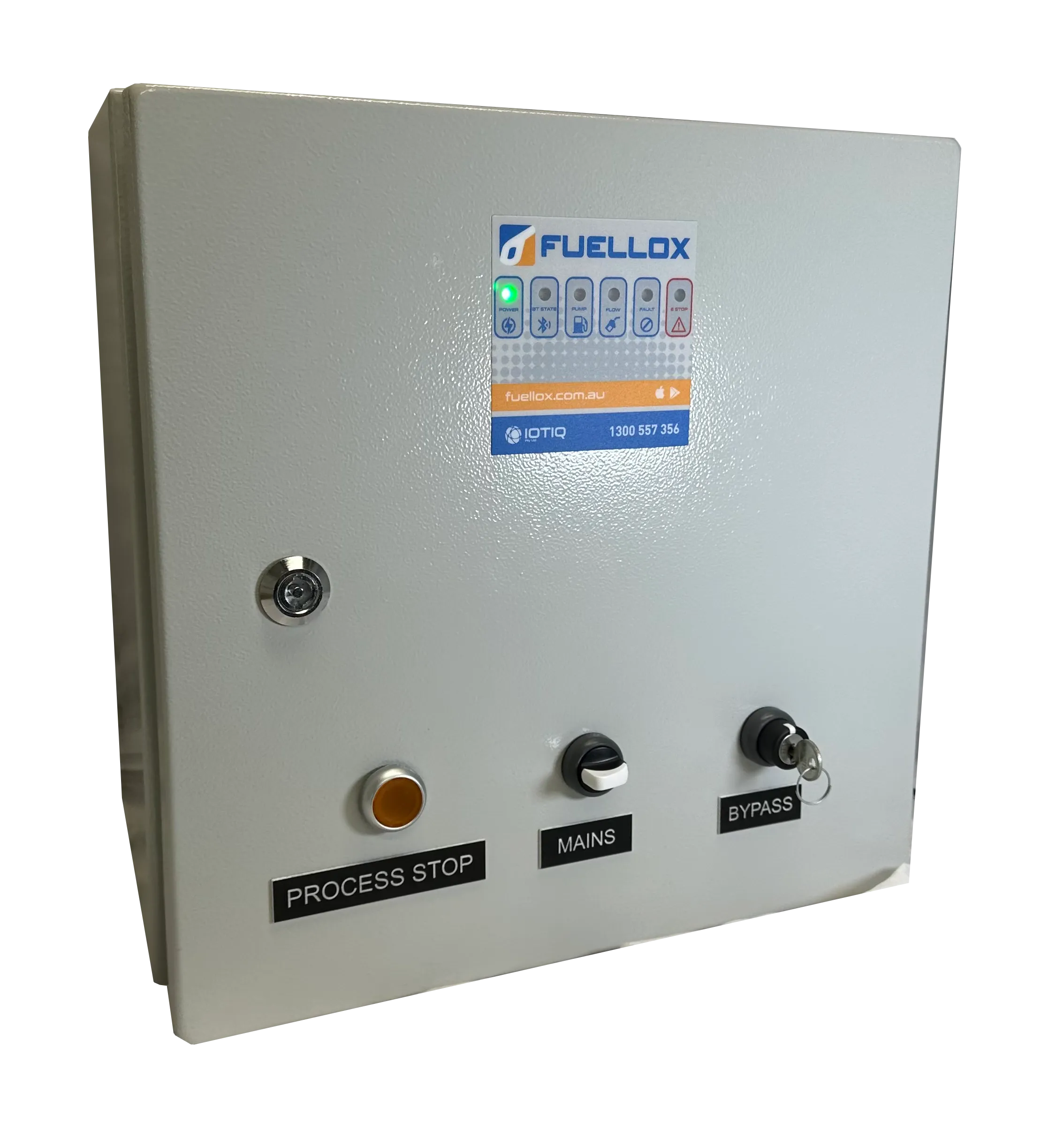
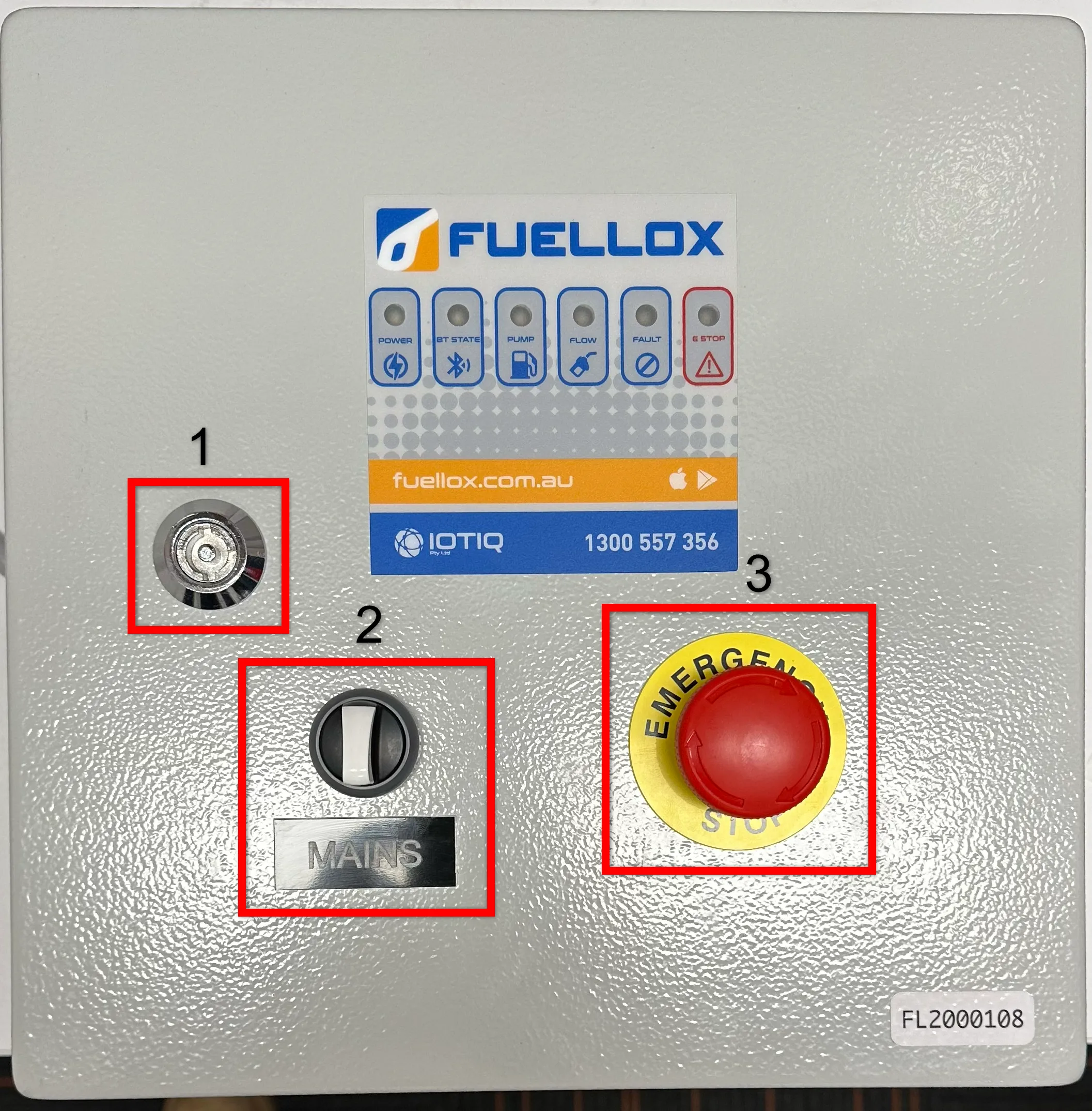
Controls
The Fuellox HD CLS interface consists of several controls that are part of the system for managing the operation effectively. The interface includes the following elements:
1. Capture Key: Used to lock the unit and prevent unauthorized access or tampering with the system’s settings.
2. Emergency/Process Stop: Instantly halts operations, used in emergencies or during maintenance to stop the system’s process.
3. Mains: Controls the main power supply to the unit, used to turn the system on or off.
4. Bypass: Allows users to override standard operation, often for maintenance or special configurations where the usual control logic is bypassed.
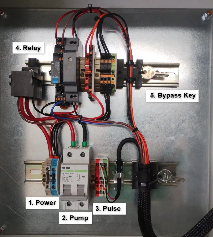
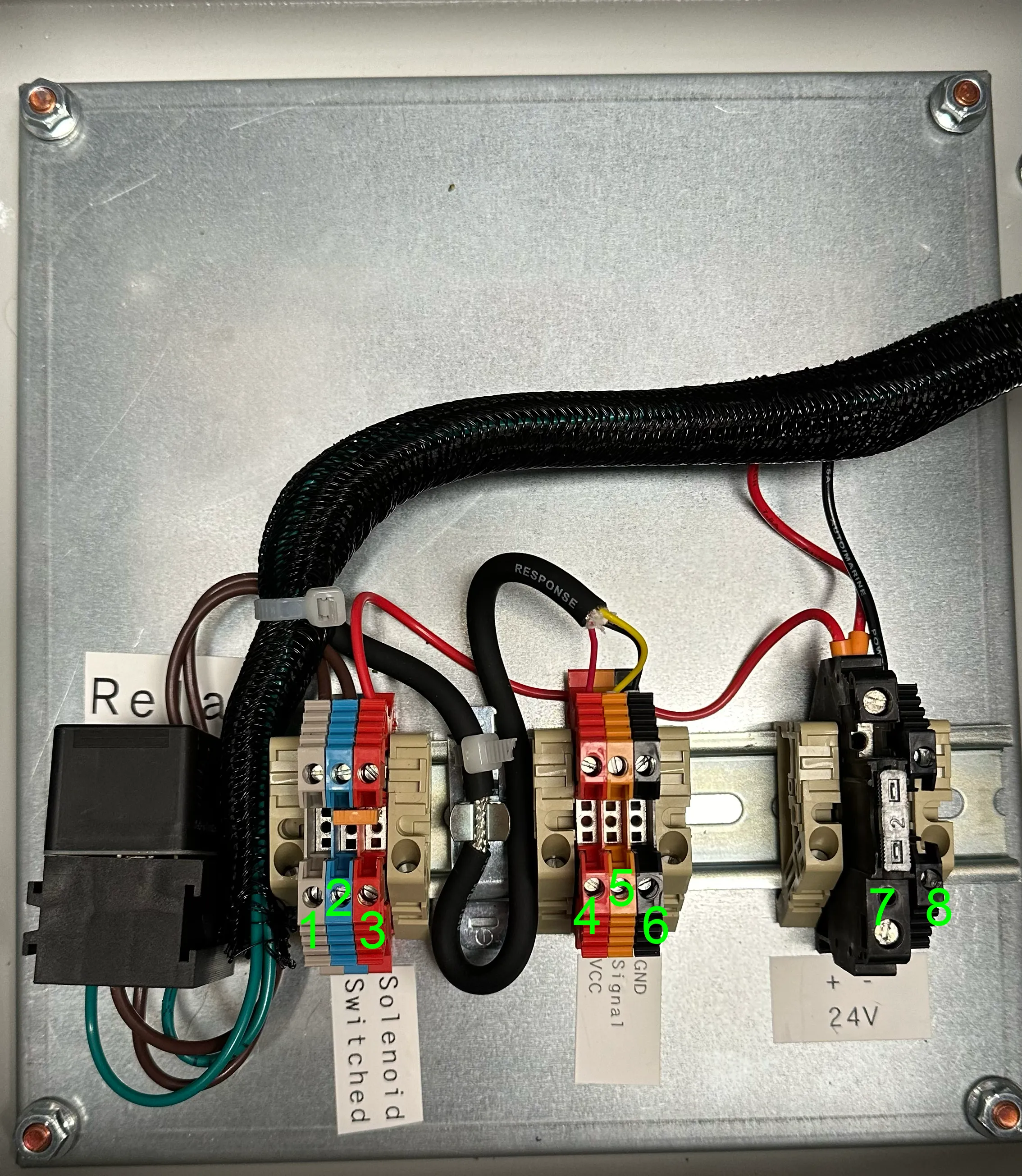
Wiring and Components
Key components highlighted in the image include:
1. Power: The main power component that ensures the unit receives the necessary power supply.
2. Pump: Controls the pump functionality of the system.
3. Pulse: Manages the pulse signal required for the operation.
4. Relay: Controls the switching of electrical circuits in the system.
5. Bypass Key: A safety and control mechanism to allow for system bypass when needed.
3. Fuellox HD Custom (LCR meters)
In some cases, the Fuellox HD system is customized to meet specific operational requirements. The configuration shown here includes an isolation feature and a secure key bypass, with the emergency stop (E-Stop) placed elsewhere on the truck.
This version is specifically designed to operate with an LC Meter. The LC Meter plays a critical role by activating power to ground, which is essential for starting the pump. In addition to this, the unit controls a relay to ensure proper pump control and operation.
A similar wiring configuration can also be used to operate an air or pneumatic solenoid for non-electric pumps, ensuring flexibility in handling various types of pumps.
Controls:
1. Key Lock: This lock ensures the system is accessible only by authorized personnel, providing an extra layer of security to prevent unauthorized access.
2. Mains Button: The Mains button is used to control the main power supply to the unit, allowing you to turn the system on or off as needed.
3. Bypass Key: The Bypass key enables the user to override standard operation, typically used during maintenance or special operations when normal control needs to be bypassed.
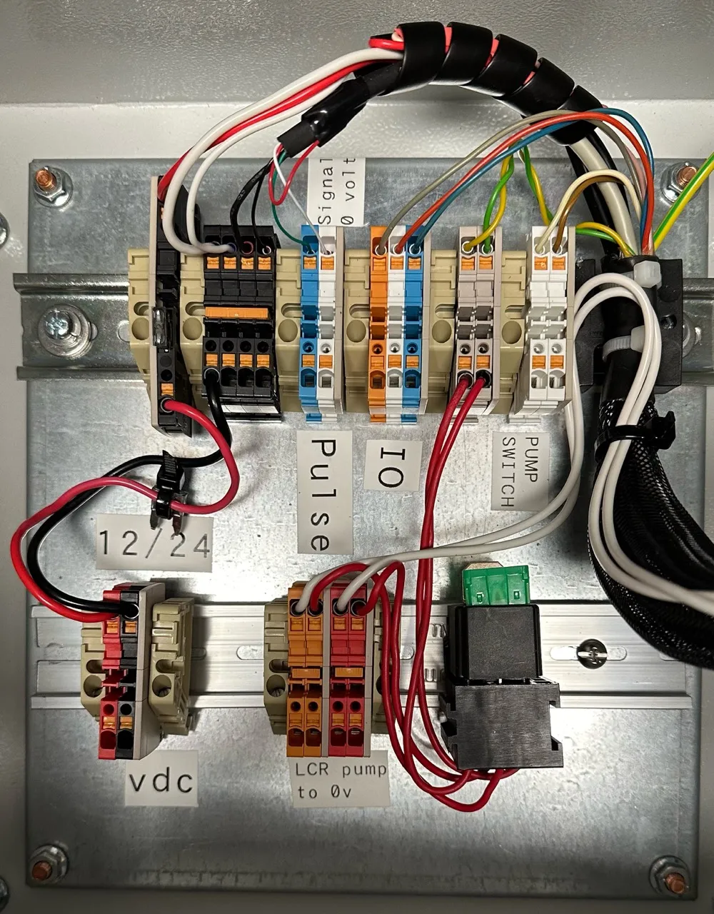
Wiring Details
To complete the setup, the following wires need to be connected:
| Connector | Description |
|---|---|
| VDC Red | Connects to vehicle’s positive power source (12/24V DC). |
| VDC Black | Connects to vehicle’s negative power source. |
| Pump Active Red/Orange | Sends pump control signal to ground. |
| Pulse Blue | Connect to LCR Pin 53 for pulse signals (Note 1). |
| Pulse Blue/White | Connect to LCR Pin 47 for pulse signals. |
| BLE (not shown) | Connects to Bluetooth antenna for wireless communication. |
| IO | Unused input/output connection for future use. |
| Nozzle Switch | Optional connection for nozzle or pump switch control. |
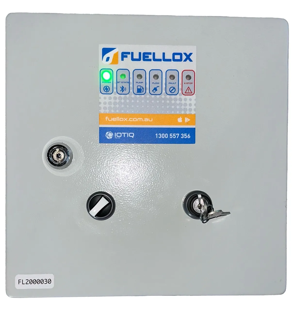
4. Fuellox HD (DFV Meter)
The Fuellox HD (DFV Meter) provides advanced functionality for controlling various equipment with enhanced monitoring features. It is equipped with a robust design that ensures efficient operation and easy integration into heavy-duty systems.
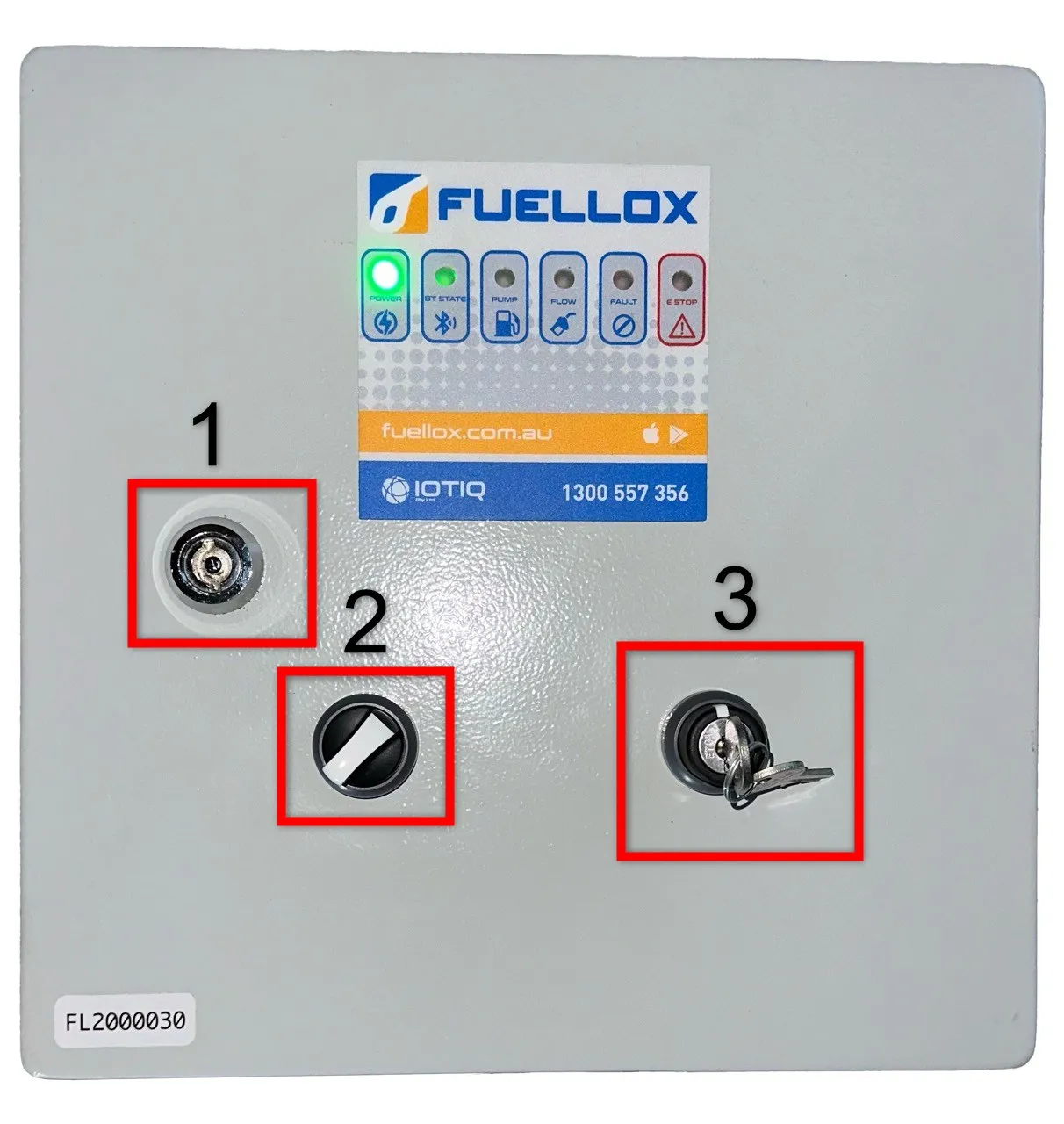
Controls:
1. Key Lock (Bypass): The key lock secures the system, allowing only authorized personnel to operate it, ensuring safety and preventing unauthorized access.
2. Mains Button: This button is used to turn the system’s power on or off, controlling the main power supply.
3. Emergency Stop Button: This button is pressed to immediately halt the system in case of an emergency or for maintenance purposes.
Wiring Details
The wiring configuration for the Fuellox HD (DFV Meter) is detailed below. Please ensure all connections are securely made and follow the wiring instructions carefully for optimal performance:
| Fuellox Pin | Description |
|---|---|
| 1 | Controls the activation of the pump. |
| 2 | Provides power to the pump control circuit. |
| 3 | Additional power for the pump control. |
| 2-3 | Pins 2 and 3 are bridged to maintain consistent power. |
| 4 | Supplies power to the Hall Effect meter. |
| 5 | Sends pulse signals for flow or speed measurement. |
| 6 | Provides ground reference for pulse signals (pulse 0v) |
| 7 | Receives fused 12/24V DC power input. |
| 8 | Main ground connection (Gnd 0v) for the system. |
After completing the wiring connections as outlined in the table above, proceed with the following steps as follows:
Solenoid
To properly connect the solenoid, follow these steps:
- Wire Pin 1 to the solenoid and return it to ground within the Fuellox enclosure or chassis.
Optional:
- Remove the bridging connector.
- Run the solenoid loop from Pin 1 back to Pin 2.
- Supply an external power source from the vehicle power.
Flow Meter
To ensure smooth operation with the flow meter:
- Enable the Liquip pulse output on the DFV.
- Wire the DFV Pulse Output to Pin 5.
- Wire the DFV Pulse 0V to Pin 6.
Power Supply
For power supply integration:
- Hook up the vehicle power to:
- Pin 7 (positive)
- Pin 8 (negative)
Antenna Installation
- Ensure proper wiring of the Fuellox BLE Antenna to the connector.
- Mount the antenna at a high point on the vehicle for optimal performance.
- Avoid drilling into the Fuellox enclosure when installing the antenna.
Applications
The Fuellox HD series is ideal for various applications, including:
1. Fuellox HD (V1): Used in Colas Crew Trucks for efficient fuel dispensing and management.
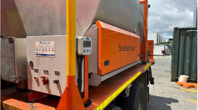
2. Fuellox HD (V2): Deployed in Earthworx Service Trucks for reliable and durable fuel management solutions in demanding environments.
For the detailed installation guide, please visit the HD installation guide.