
R1 Installation Guide
The Fuellox Portable (Compact R1 SKU) is a compact and efficient fuel management solution unit designed for flexible and temporary fuel dispensing setups. This variant, FLX-COMPACT-R1, includes an additional relay—denoted by [R1] in the part number—making it ideal for installations requiring pump control. It seamlessly integrates with existing fuel systems, offering precise tracking, enhanced security, and real-time reporting via the Fuellox app.
Pulse Meter
In this scenario, a Piusi K24 Pulse Meter is to be installed.
The accompanying image shows that the mechanical meter and filter are suspended solely from the 1” pipework. This configuration is not ideal, as the pulse meter is not designed to bear the weight of other components.
For installations of this nature, the following is recommended:
-
Install the pulse meter between the filter and the mechanical meter.
-
Fabricate and fit a welded bracket to support both the filter and the mechanical meter.
This will ensure the pulse meter remains free of mechanical stress and is not subjected to the weight or movement caused by the connected hose.
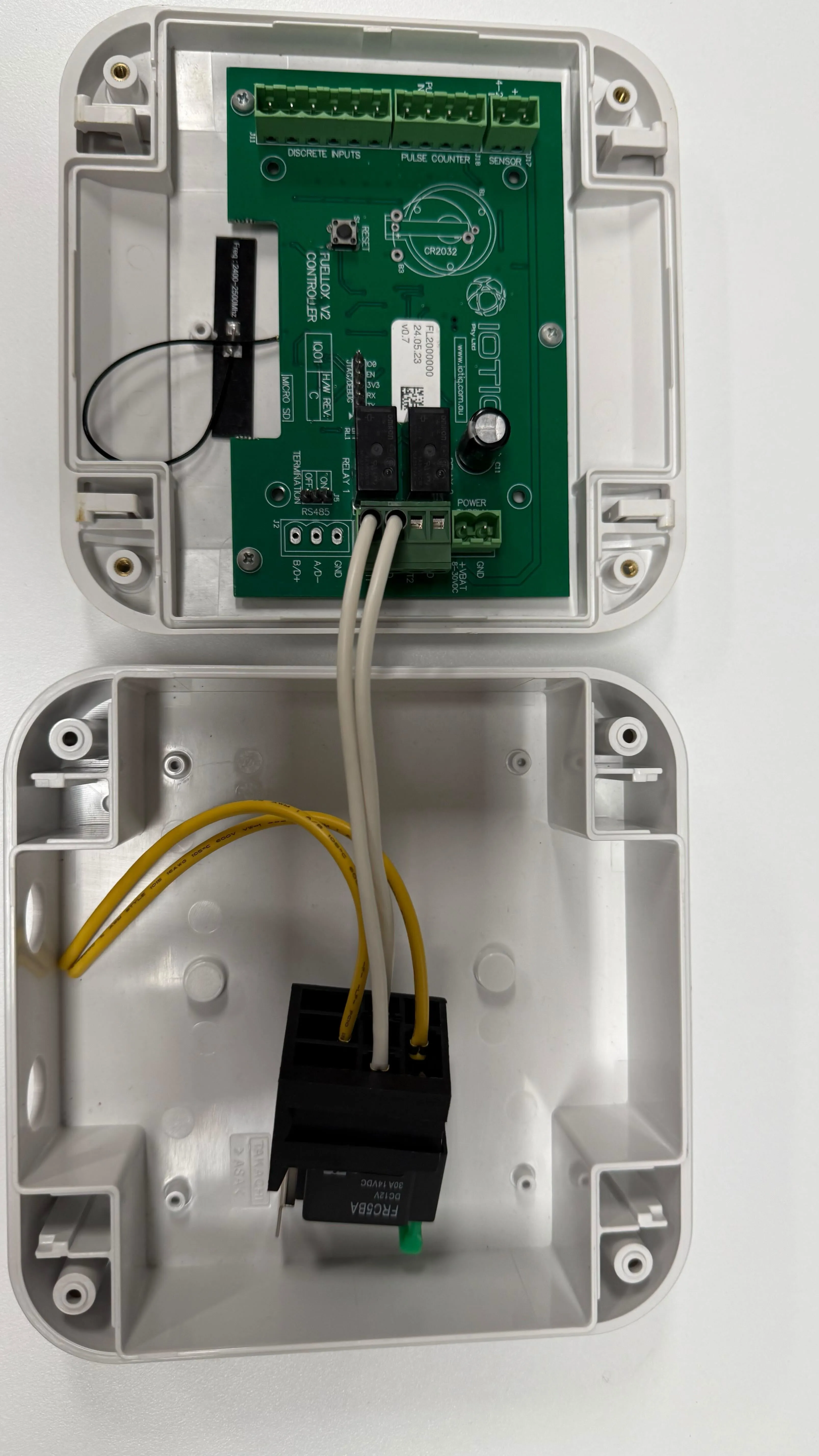
Main Power
A regulated 12V DC power supply is required for the Fuellox input.
| Jumper Block | Pin Number | Pin Label | Name | Description |
|---|---|---|---|---|
| J9 | 1 | GND | Mains 0V | 12V -ve |
| J9 | 2 | +VBAT | Mains 12V | 12V +ve |
Pump Control
The 12V DC supply to the pump must be routed through the Fuellox Relay for proper operation.
Make sure that an appropriate cable is used—one that can safely handle the voltage and current requirements of the pump.
The diagram below illustrates a basic wiring configuration where the pump is powered directly through a manual switch:
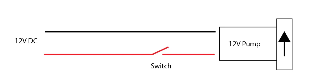
In this setup, power flows directly from the 12V DC source to the pump via the switch.
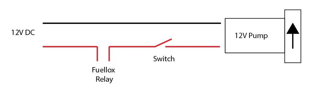
The following diagram demonstrates how the power can be diverted through the Fuellox Relay. This configuration enables Fuellox to control the pump electronically. The switch should remain in the ON position, allowing Fuellox to start and stop the pump as required:
This image displays the Fuellox relay module. The relay operates in a simple open or closed state—there is no input or output signal processing.
- Open (default): The circuit is disconnected when the relay is not energised.
- Closed (energised) : The circuit is connected when the relay is activated.
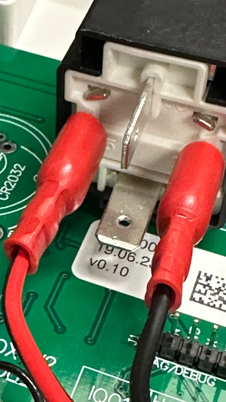
This mechanism enables Fuellox to control connected components, such as pumps, by switching power based on system commands.
Surface Mount Relay Wiring Guide
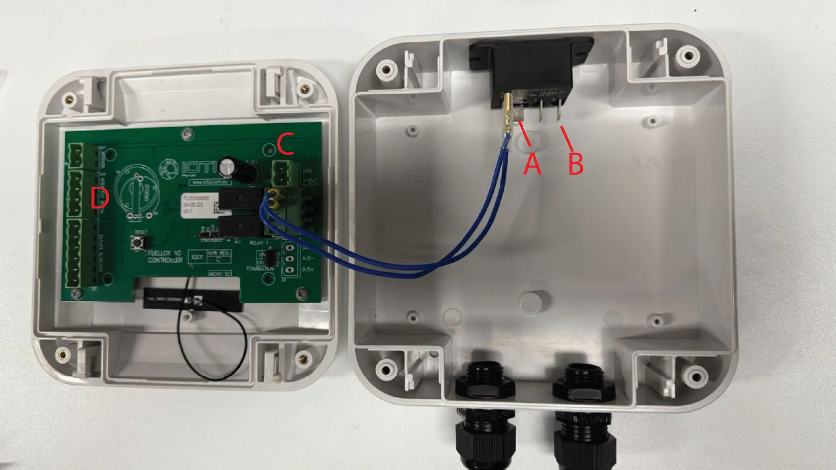
| Socket | Pin | Mark | Function | Notes |
|---|---|---|---|---|
| None | None | A | Pump Active Supply | |
| None | None | B | Pump Active Switched | |
| J19 | +VBAT | C | Power 12V | |
| J19 | GND | C | Power 0V | |
| J18 | +V | D | Hall meter power VCC | |
| J18 | PULSE | D | Reed or Hall Signal | |
| J18 | GND | D | Reed or Hall 0V |
Meter Wiring
Flomec: [Hall, 3 Wires] J18 +V, PULSE, GND
IOTIQ Turbine: [Hall, 3 Wires] J18 +V, PULSE, GND
Piusi Meters: [Reed, 2 Wires] PULSE, GND
Options
The following optional features are available for extended functionality. Refer to the linked sections below for wiring and configuration details: