
240V AC Wiring Guide
Mains-powered pumps must be installed by a qualified electrician to ensure safety and compliance.
This guide provides a basic wiring suggestion. Depending on the pump type and circuit control requirements, modifications to this concept drawing may be necessary.
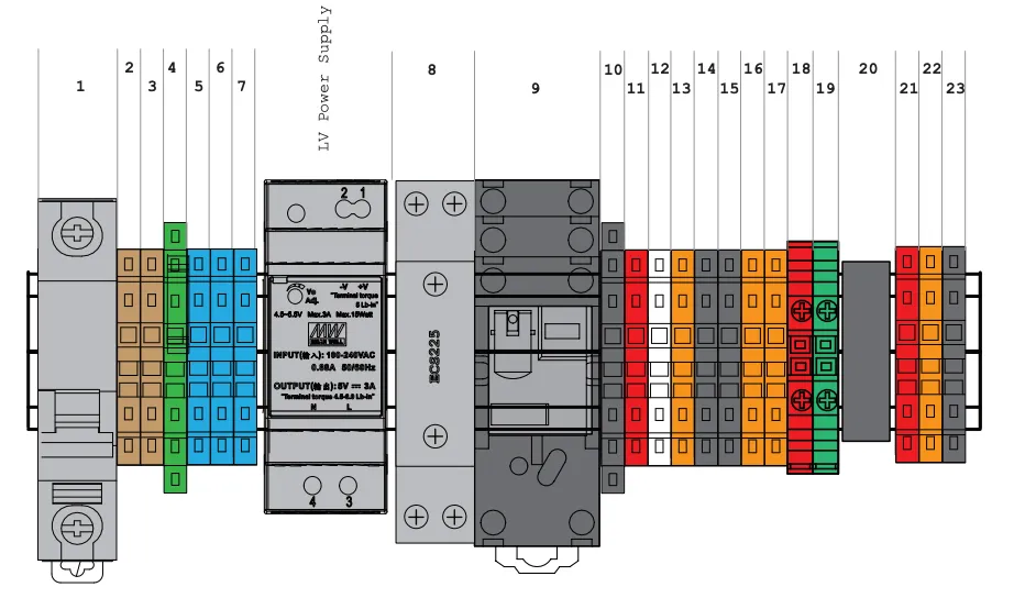
240V AC Wiring Overview
| # | Block Colour | Description | Connection |
|---|---|---|---|
| 1 | Grey Switch | Isolator Switch Power Isolator, Load | Main Load Supply |
| 2 | Fawn | Load Distribution Bridged | Main Load Supply |
| 3 | Fawn | Load Distribution Bridged | Main Load Supply |
| 4 | Green/Gold | Main + Pump Earth | Main + Pump Earth |
| 5 | Blue | Neutral Bridged | Main Neutral |
| 6 | Blue | Neutral Bridged | Pump Neutral |
| 7 | Fawn | Pump Switched Active | Pump Load |
| 12v | Dark Grey | Meanwell DC Power Supply | 240V Supply |
| 8 | Grey Contactor | Hager ECS225 | |
| 9 | Black | Relay (1 to 4 pole) depends on product | |
| 10 | Black - Fused 1A | 12V DC Ground | 12V 0V |
| 11 | Red | 12V DC Supply | 12V Supply |
| 12 | White | Low Voltage Nozzle Active | Fuellox IO |
| 13 | Orange | Normally Open EStop | Fuellox IO |
| 14 | Black | Nozzle 0V | Fuellox IO |
| 15 | Black | Normally Open EStop 0V | Fuellox IO |
| 16 | Orange | Normally Close EStop Loop | Relay Active |
| 17 | Orange | Normally Close EStop Loop | Relay Active |
| 18 | Red Screwed | Level Instrument Supply 4-20mA | Fuellox 4-20mA Vcc |
| 19 | Green Screwed | Level Instrument Sensor 4-20mA | Fuellox 4-20mA Vcc 0V |
| 20 | Shield Ground | Shielding Ground & Strain Relief | |
| 21 | Red | Flow Meter Supply VCC | Hall Supply |
| 22 | Orange | Flow Meter Sensor | Hall/Reed Sensor |
| 23 | Black | Flow Meter 0V | Hall/Reed 0V |
240V AC Wiring Diagram
The overview diagram illustrates the wiring connections for a typical 240V AC system.
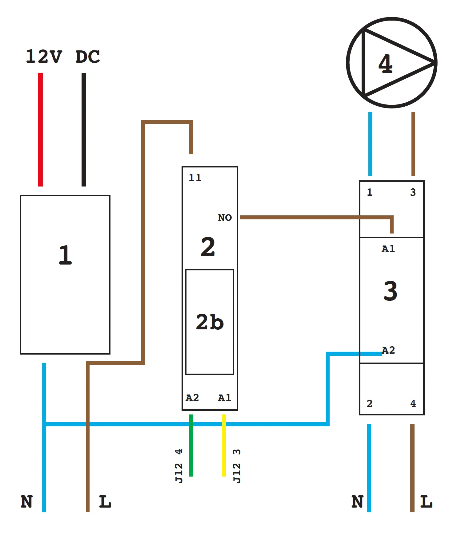
Parts List
| Number | Item | Brand | Part Number Suggested | Vendors |
|---|---|---|---|---|
| 1 | Power Supply | Meanwell | HDR-30-12 | Jaycar |
| 2 | Relay | Weidmuller | DRI-SERIES 1CO 12A | Tro Pacific |
| 2b | 12V DC Coil | Weidmuller | DRI-SERIES 12VDC 1CO 10 AMP* | Tro Pacific |
| 3 | Contactor | Hager | ECS-225 | CNW, MMEM, Haymans |
| 4 | Pump Motor | Various | 240V AC 10Amps | N/A |
24V Supply
In certain scenarios, using a 24V DC power supply in combination with a relay may be more convenient.
Power supply current
The power supply’s current requirements primarily depend on the circuit’s demand. In most cases, a 1.5A power supply is sufficient to operate Fuellox equipment effectively.
AC Pump control variants
There are various standards for AC wiring depending on the system design, purpose and generation. There are variations from batch to batch. These variations come about due to availability of components.
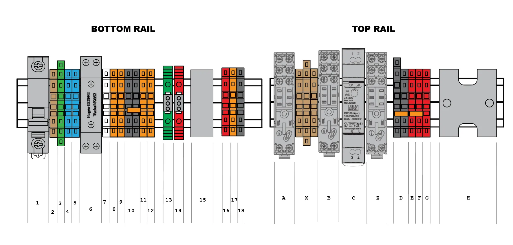
| RAIL | Label | Description | Notes |
|---|---|---|---|
| Bottom | 1 | Safety Isolator | Switch of when cabinet is open |
| 2 | Active (optional) | ||
| 3 | Earth | ||
| 4 | Neutral | ||
| 5 | Neutral | ||
| 6 | Contactor | Hager ECS225 or equivalent | |
| 7 | IO - Input 1 | ||
| 8 | IO - Input 2 | ||
| 9 | Spare/Optional | May not be present in all builds | |
| 10 | IO - 0V | ||
| 11 | EStop Normally Closed | Loop | |
| 12 | EStop Normally Closed | Loop | |
| 13 | Level Signal | ||
| 14 | Level VCC | ||
| 15 | Signal Shield + Strain Relief | ||
| 16 | Hall Power VCC | ||
| 17 | Hall/Reed Signal | ||
| 18 | Hall/Reed 0V | ||
| 19 | Optional Aux 12V | Not shown | |
| Top | A | Relay 1 | 1 or 2 Pole Relay |
| X | Neutral Distribution Block | Not present in all models | |
| B | Relay 1 | 1 or 2 Pole. Not present in all models | |
| C | 240V AC to 12V DC power supply | ||
| Z | Relay 3 | 1 or 2 Pole. Not present in all models | |
| D | GND/Earth Distribution | ||
| E/F | 12V DC Distribution | ||
| G | Bypass channel | ||
| H | Strain Relief |