
HDU - Heavy Duty Universal
Fuellox HDU (Heavy Duty Universal) is a rigid and versatile fuel management system designed for heavy-duty applications, ideal for high-usage environments such as service trucks, large trailers, and areas with limited weather protection. The Fuellox HD is built to handle tough conditions, with a strong steel enclosure and a Universal power module.
Capabilities
Following are the capabilities of the Heavy Duty:
- Setup and calibration through a mobile app for ease of use.
- No SIM cards or FOBs required for operation.
- Over-the-air firmware updates for long-term support and performance improvements.
- Optional interface for Level, Emergency Stop (Estop), Bypass, Nozzle Switch, and more functionalities.
Compatibility
Following are the compatibilities of the Heavy Duty:
- Operates on 12V or 24V DC or 110V or 240V AC power sources.
- Compatible with both 2-wire Reed and 3-wire Hall Effect pulse meters.
- Supports a wide range of electrical pumps or solenoids for pneumatic and hydraulic pumps.
- Requires use of Fuellox High Gain BLE Antenna for optimal performance.
Fuellox HDU
The Fuellox HDU is housed in a robust steel enclosure measuring 300mm x 300mm with a typical depth of 150mm, although a 200mm depth option is also available.
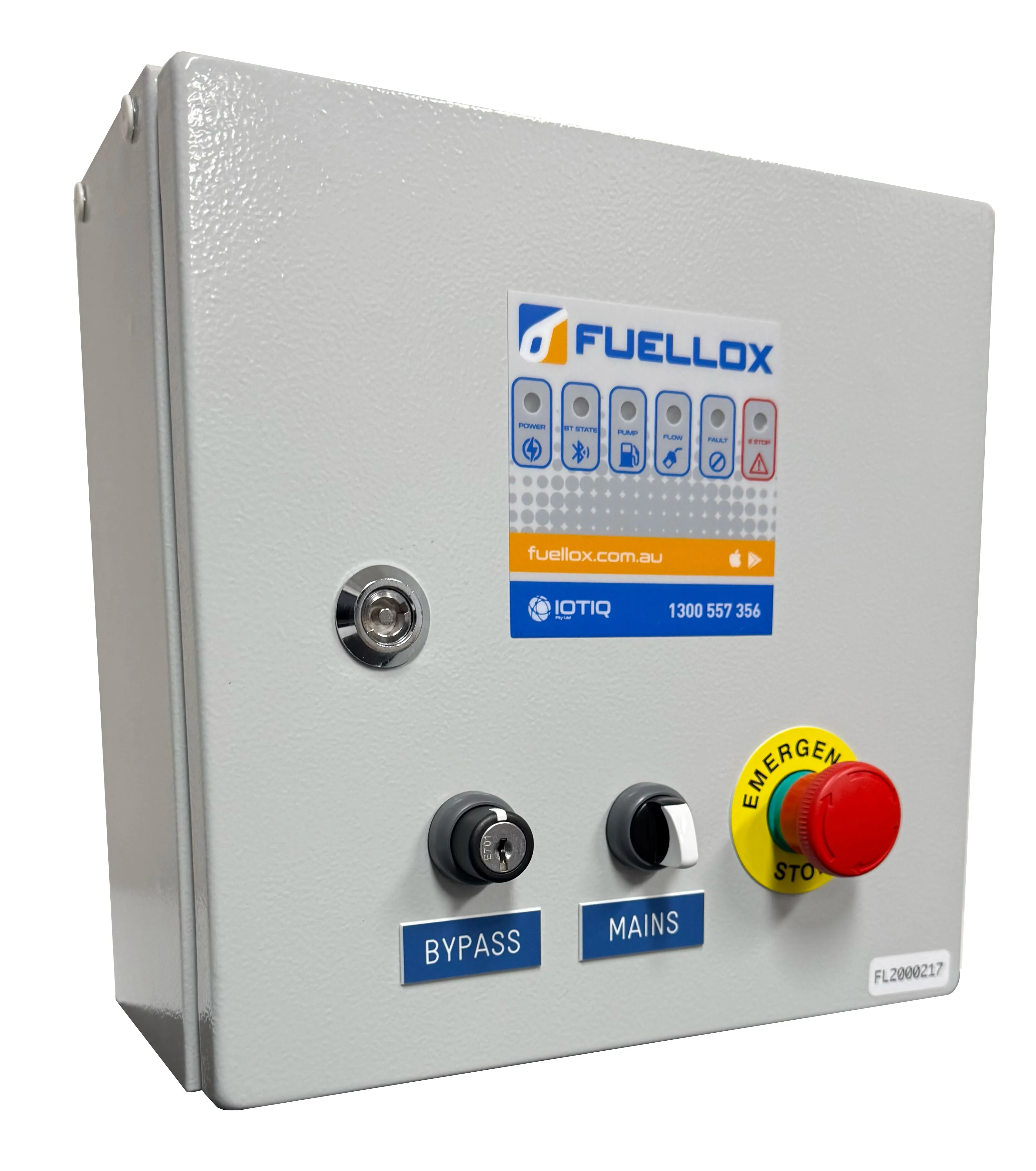
The Fuellox HDU appears the same as a regular Fuellox HD from the outside.
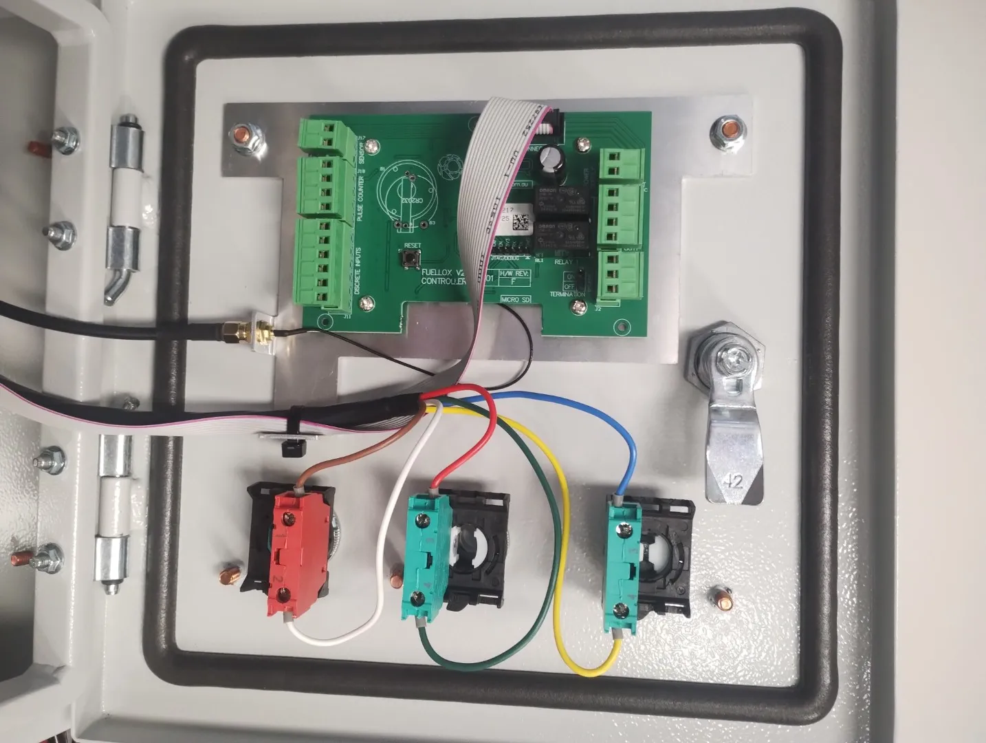
HDU Door Wiring
Note: the antenna is connected, and cover plate removed
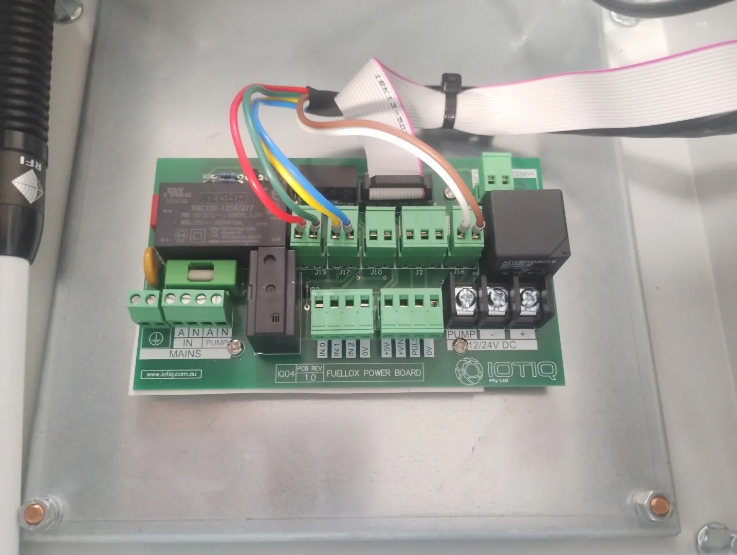
HDU Main Power Board
Installation Wiring
Installation Steps
- Mount the Fuellox HD enclosure.
- Remove the cover plate from the bottom of the enclosure.
- Drill the cover plate to allow cable entries as required using suitable cable glands. Pass all cables through the glands to maintain IP integrity.
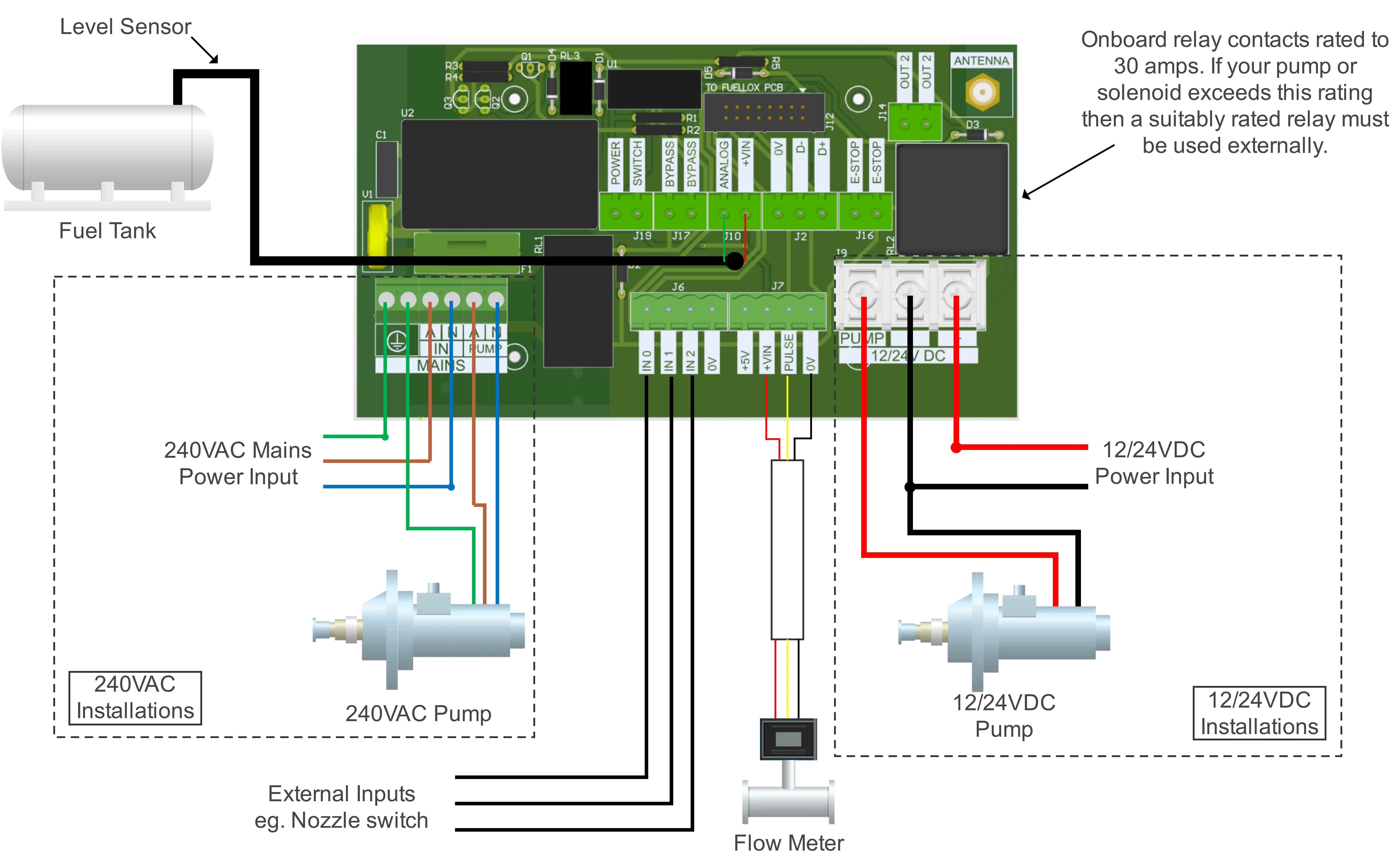
- Follow the connection diagram below depending on your voltage requirements.
- Connect the flow meter to J7 on the board as indicated. It is recommended to use screened cable to reduce the impact of electrical noise on the signal.
- If required, fit the fuel tank level monitor to J10 on the board as indicated. https://docs.fuellox.com.au/products-fuellox/accessories/level/
- Connect the nozzle switch to one of the inputs on J6 on the board. The inputs are user-configurable in the config tab in the app and any of the three inputs can be used and configured as required. They are active low and are wired between the input and ground. https://docs.fuellox.com.au/products-fuellox/accessories/nozzle-switch/
- Mount the Bluetooth antenna to the outside of the enclosure ensuring the IP integrity of the enclosure is maintained.
- Re-fit the cover plate on the base of the enclosure and tighten all the cable entry glands for weather sealing.
- Once the installation is complete, carry out a dispense action by following this guide: https://docs.fuellox.com.au/gettingstarted/f-first-use/
12/24V DC systems
Connect the DC Supply and Pump to the 12/24V supplied.
A max current of 30A is supplied via the Fuellox unit. For higher current pumps an additional relay is required.
For solenoid applications, simply connect the solenoid in place of the pump.
110/240V AC systems
Connect the AC Supply and Pump to the Mains Side. Be sure to maintain the earth connections.
3 Wire Pulse Meters (Hall)
| Pin | Wire |
|---|---|
| J7 +VIN | Meter Power |
| J7 Pulse | Meter Signal |
| J7 0V | Meter 0V |
2 Wire Pulse Meters (Reed)
| Pin | Wire |
|---|---|
| J7 +VIN | Not Required |
| J7 Pulse | Meter Signal |
| J7 0V | Meter 0V |
Nozzle Switch
Fuellox works with Normally Closed nozzle switches. ie Nozzle lift opens circuit
| Pin | Wire |
|---|---|
| J6 IN1 | Brown Wire |
| J6 0V | Blue Wire |
Fuellox Level Module
| Pin | Wire |
|---|---|
| J10 +VIN | Red Probe Wire |
| J10 Analog | Green Probe Wire |
Controls:
- Bypass: Secures the system to prevent unauthorized access and ensures only authorized personnel can operate the unit in bypass mode.
- Mains: On/Off to the Fuellox System. this switch does not isolate power on the power modile
- Emergency Stop: Emergency pump/system shut off
Notes on E Stop & Bypass
The EStop will still operate in Bypass mode.
When the E Stop is released, the pump will not start.
Turn off the Main Switch to reset the power board.
BLE Antenna
Connect the Fuellox Antenna to the BLE connection point prior to use.
The Antenna connection point is behind the door cover, facing the hinge.
Final Wiring Stage
Ensure all wires are secured well to the provided train relief plate.
Tighten all glands.
For 240V AC systems ensure all elements are adequately earthed including the enclosure.
Secure the door.
Commissioning
- Power up the unit.
- Ensure the Pump can be started/stopped from the app.
- Calibrate the Meter.
- Configure the Level Module where supplied.
- Test the system thoroughly prior to hand over to the end users.
- Confirm all data is recorded as expected on the Fuellox Cloud.
Return to Getting Started