
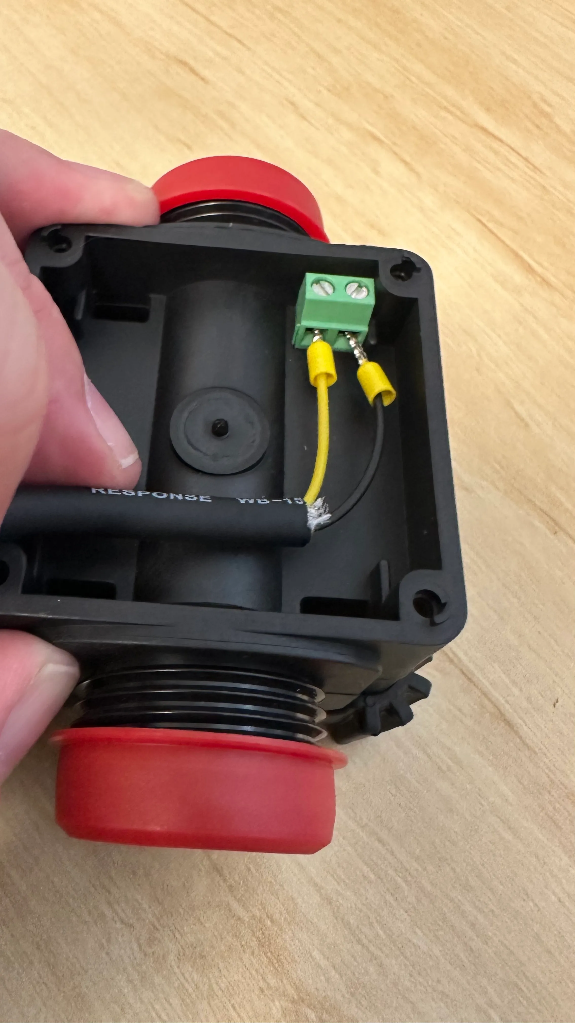
R3 Installation Guide
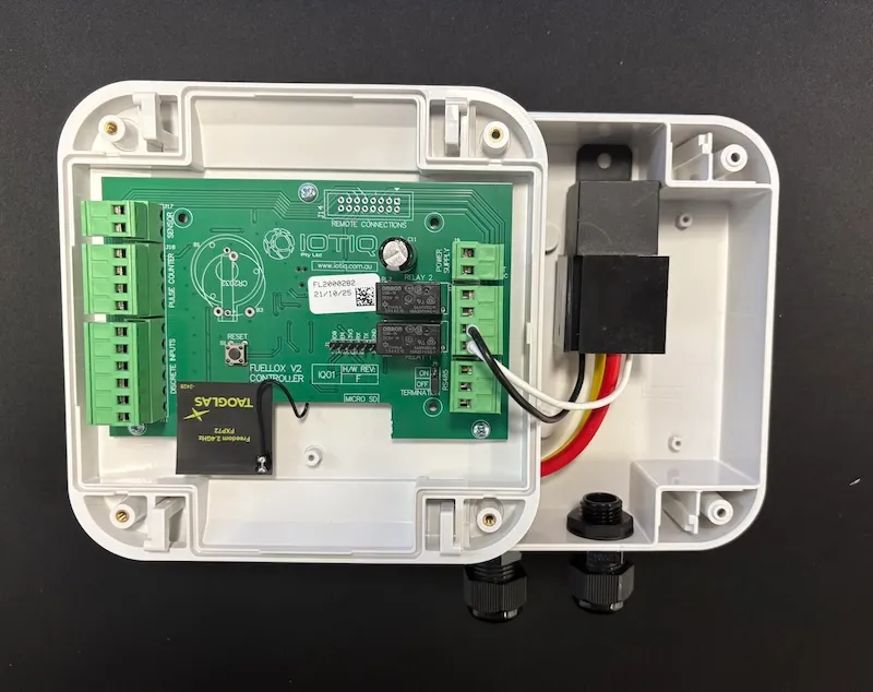
The Fuellox Portable (Compact R3 SKU) is a compact unit with an additional high current relay for 12/24VDC pump control.

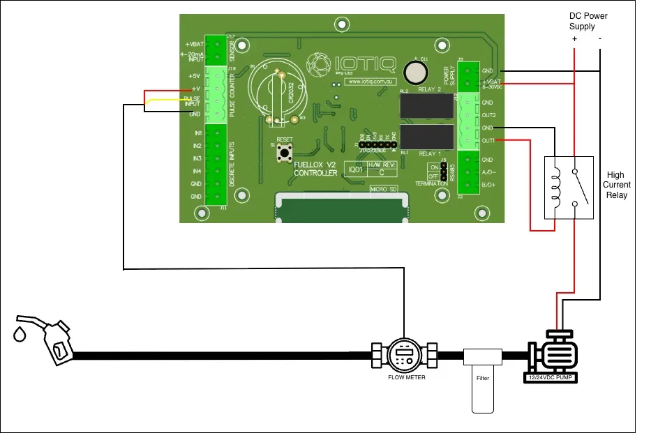
Main Power
A regulated 12V DC power supply is required for the Fuellox input.
| Jumper Block | Pin Number | Pin Label | Name | Description |
|---|---|---|---|---|
| J9 | 1 | GND | Mains 0V | 12V -ve |
| J9 | 2 | +VBAT | Mains 12V | 12V +ve |
Pump Control
The 12V DC supply to the pump must be routed through the Fuellox Relay for proper operation.
Make sure that an appropriate cable is used—one that can safely handle the voltage and current requirements of the pump.
The diagram below illustrates a basic wiring configuration where the pump is powered directly through a manual switch:
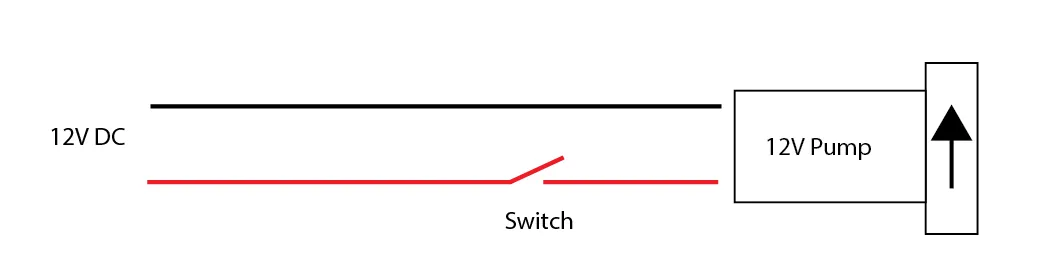
In this setup, power flows directly from the 12V DC source to the pump via the switch.
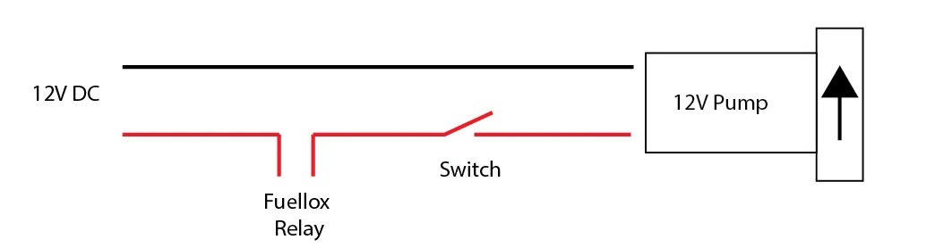
The following diagram demonstrates how the power can be diverted through the Fuellox Relay. This configuration enables Fuellox to control the pump electronically. The switch should remain in the ON position, allowing Fuellox to start and stop the pump as required:
Pulse Meter
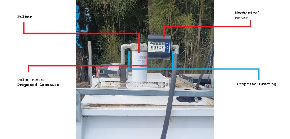
The accompanying image shows that the mechanical meter and filter are suspended solely from the 1” pipework. This configuration is not ideal, as the pulse meter is not designed to bear the weight of other components.
For installations of this nature, the following is recommended:
-
Install the pulse meter between the filter and the mechanical meter.
-
Fabricate and fit a welded bracket to support both the filter and the mechanical meter.
This will ensure the pulse meter remains free of mechanical stress and is not subjected to the weight or movement caused by the connected hose.
Proposed Installation Layout
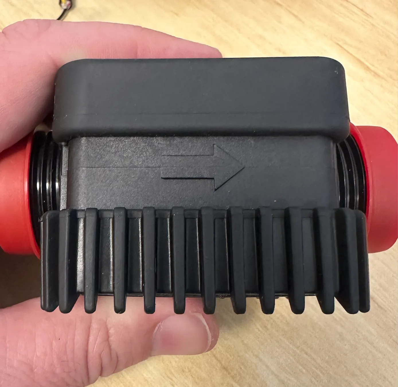
Pulse Meter Installation
Make sure the flow direction of the pulse meter is correctly aligned before installationfor accurate and reliable operation.
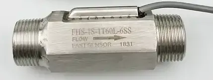
SU304 Turbine Meter
The SU304 is a Hall Effect turbine meter. It connects to the Fuellox unit using three wires, as outlined below. Please note that these meters are not supplied with shielded cables.
SU304 Turbine Meter wiring Details
| Jumper Block | Pin Number | Pin Label | Color | Name | Description |
|---|---|---|---|---|---|
| J18 | 2 | +V | Red | Power | |
| J18 | 3 | Pulse Input | Yellow | Pulse Signal | |
| J18 | 4 | GND | Black | Pulse Meter 0V |
The calibration factor for this meter is 67.068 pulses per litre (pulse/L).
Piusi K24
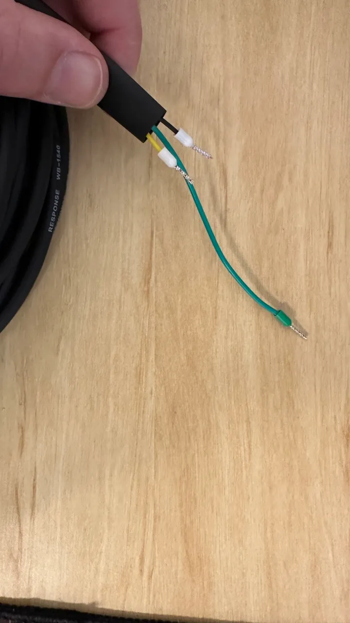
Reed pulse meters are connected using Signal and Ground wires. While optional, it is strongly recommended to use a shielded cable for improved signal integrity and noise reduction.
The image below illustrates a shielded cable, where an additional lead is connected to the shielding layer within the cable assembly.
Pulse Meter Wiring Details
The table below outlines the recommended pin assignments for connecting a pulse meter to the system. Use a shielded cable for best performance, with the shield connection being optional but recommended.
| Jumper Block | Pin Number | Pin Label | Name | Description |
|---|---|---|---|---|
| J18 | 3 | Pulse Input | Pulse Signal | |
| J18 | 4 | GND | Pulse Meter 0V | |
| J11 | 6 | Shield | Shield Wire | Optional |
Connect the other ends of the wires to the corresponding terminals on the pulse meter body, ensuring proper signal and ground alignment.
The calibration factor for this meter is 87.73 pulses per litre (pulse/L).
Options
The following optional features are available for extended functionality. Refer to the linked sections below for wiring and configuration details: